Thanks! I will add link to your forum at the beginning of this thread.
The stiffness of the enclosure is certainly important to avoid enclosure resonance at low frequencies. But I think it is the damping coefficient of the material that gives an indication of how much energy is lost during deflection of the enclosure and how much is returned to the system. Compared to wood, most metals are low loss, but there are some exceptions like certain stainless steel alloys.Stiffness and impedance peak is related to the elasticity of the enclosure...The relationship is perhaps found in elasticity modulus differences between the enclosure materials.
The stiffness of the enclosure is certainly important to avoid enclosure resonance at low frequencies. But I think it is the damping coefficient of the material that gives an indication of how much energy is lost during deflection of the enclosure and how much is returned to the system. Compared to wood, most metals are low loss, but there are some exceptions like certain stainless steel alloys.
I think that you are right. Knowing both parameters, stiffness and damping is probably the way to do. But as you know the methods to create an enclosure are many. And the stiffness of any container is linked to the methods used to keep it stiff.
Why people can spend a good part of their career on seemingly simple things.
The simple things are not really all that simple right!
I see it is an advance on the good old T/S model. First mentioned by Leach long ago?
Can somebody add a few words about how "semi-inductance" is "caused"? Just in the driver or also influenced when mounted? What steps mechanically collapse it to conventional inductance and is that a good design purpose for driver designers or just something for crossover designers to remember?
B.
Can somebody add a few words about how "semi-inductance" is "caused"? Just in the driver or also influenced when mounted? What steps mechanically collapse it to conventional inductance and is that a good design purpose for driver designers or just something for crossover designers to remember?
B.
Last edited:
First investigated and physical theory proposed by Vanderkooy in 1989.
See Post #15 for references *.pdf with link to free download along with many other relevant papers.
If you look at the measured impedance of a woofer without any shorting rings, you will see the phase of the impedance above resonance tends to be roughly 45deg over a broad range, rather than quickly approaching 90deg of a pure inductance. See Attachment #1 in Post #30.
In a few words, the cause is the frequency dependent eddy-current losses in the unlaminated pole piece. It is a property of the woofer motor construction and has nothing to do with mounting or enclosure. Use of laminated pole piece would largely avoid the semi-inductance, but result in much higher inductance and rolled off high-frequency response, so not a good idea. The approach taken by most higher quality woofer designs is to incorporate shorting rings to keep the impedance flatter and more resistive(lower phase angle), extending the high frequency response as well as reducing distortion from inductance modulation.
The 2011 model proposed by Thorborg and Futtrup that is slowly finding its way into more and more software packages incorporates not only the semi-inductance behavior, but can also account for shorting devices inside and/or outside the magnetic gap.
Last edited:
Nice brief explanation. If you don't mind, I'd like to include it in the next update to the my semi-inductance page at The Subwoofer DIY Page - Semi-Inductance.
First investigated and physical theory proposed by Vanderkooy in 1989.
See Post #15 for references *.pdf with link to free download along with many other relevant papers.
If you look at the measured impedance of a woofer without any shorting rings, you will see the phase of the impedance above resonance tends to be roughly 45deg over a broad range, rather than quickly approaching 90deg of a pure inductance. See Attachment #1 in Post #30.
In a few words, the cause is the frequency dependent eddy-current losses in the unlaminated pole piece. It is a property of the woofer motor construction and has nothing to do with mounting or enclosure. Use of laminated pole piece would largely avoid the semi-inductance, but result in much higher inductance and rolled off high-frequency response, so not a good idea. The approach taken by most higher quality woofer designs is to incorporate shorting rings to keep the impedance flatter and more resistive(lower phase angle), extending the high frequency response as well as reducing distortion from inductance modulation.
The 2011 model proposed by Thorborg and Futtrup that is slowly finding its way into more and more software packages incorporates not only the semi-inductance behavior, but can also account for shorting devices inside and/or outside the magnetic gap.
Great explanation!
The shorting ring can also be a pole piece sleeve. This is done in most drivers that are a wider band device like a mid-woofer. Not really used in narrow bandwidth devices like a subwoofer.
Thanks for clear explanation. Vanderkooy (a local star*), not Leach?
Wouldn't eddy current loss be a source of non-linearity due to magnetic hysteresis or is that only in non-coppered iron cores?
As Mark said, not a big factor to grind into the model except when the band is wide.
B.
*Didn't he do a remarkable study of super-low resonance AR-like woofer drivers?
Wouldn't eddy current loss be a source of non-linearity due to magnetic hysteresis or is that only in non-coppered iron cores?
As Mark said, not a big factor to grind into the model except when the band is wide.
B.
*Didn't he do a remarkable study of super-low resonance AR-like woofer drivers?
I don’t mind at allNice brief explanation. If you don't mind, I'd like to include it in the next update to the my semi-inductance page at The Subwoofer DIY Page - Semi-Inductance.
") Feel free to include any text or attachments from this thread on your web page.
Feel free to include any text or attachments from this thread on your web page.You might add a link to this thread for questions, similar to what you have on your Horn Folding web page.
I don’t believe so, no. At least that is my assessment base on comparing semi-inductance levels of neodymium woofers with similar ceramic magnet woofers. The improvement comes when shorting devices are incorporated in the design.Can neodymium drivers, due its lower size and more dense magnetic field, improve any losses regarding eddy-current in the pole piece?
Leach did publish a paper which proposed an empirical curve fit model a bit more than a decade after the Vanderkooy paper…which he references. There were several other papers(Wright, B&K, Klippel etc) all of which reference the Vanderkooy paper but instead of incorporating the physical model they resort to various empirical curve fitting methods.Thanks for clear explanation. Vanderkooy (a local star*), not Leach?
Thorborg et al. were then ones who embraced the physics involved and expanded the model to cover other aspects like shorting devices. The importance of this is that if you use curving fitting with a physics based model to match the part of the blocked impedance curve where it is well defined above resonance, the resulting blocked impedance will be correct in the lower frequency (motional impedance) range where it effects the accuracy of enclosure modeling.
Yes, all part of the inductance related distortion that shorting devices help with.Wouldn't eddy current loss be a source of non-linearity due to magnetic hysteresis or is that only in non-coppered iron cores?
But this is not relevant for the purpose of the semi-inductance model which is improved accuracy of enclosure modeling.
I am unaware of any papers by him on low resonance woofers…several on high-BL woofers though.*Didn't he do a remarkable study of super-low resonance AR-like woofer drivers?
I’d be interested if you can identify the study you are thinking of.
I don’t mind at all
You might add a link to this thread for questions, similar to what you have on your Horn Folding web page.
Done - the page is updated.
BTW, I didn't go into it on detail on the page, but I think I ran into "proof" of the semi-inductance effect in my POC3 build several years ago. When I measured the frequency response of the POC3, the response at the upper end of the passband seemed to be a bit lower than I expected. Not so much that I had to be concerned about it, but I was wondering at the time why there was that difference between the predicted and measured response.
Updating the model with the driver's calculated semi-inductance parameters went a long way towards explaining the measured difference.
When I measured the frequency response of the POC3, the response at the upper end of the passband seemed to be a bit lower than I expected. Not so much that I had to be concerned about it, but I was wondering at the time why there was that difference between the predicted and measured response.
FR, polar response, and the like result from artful manipulation of driver design. Not worth fussing about semi-inductance to get them closer to the model which in any case doesn't get "into the weeds" of physical design.
But distortion arising from hysteresis is worth fussing about since that can't be corrected by artful manipulation in the same way. Truly wrong-headed that the T/S enterprise has focused on FR and blinded many to distortion. FR is among the least of our concerns these days with DSP or EQ everywhere.
I suppose all good magnetic materials also are good carriers of induced currents? Would old-tyme pot-shaped alnico magnet structures be less distorted? Or new concepts for synthetic magnets?
B.
Last edited:
FR, polar response, and the like result from artful manipulation of driver design. Not worth fussing about semi-inductance to get them closer to the model which in any case doesn't get "into the weeds" of physical design.
???
What does that have to do with what I said about the semi-inductance effect possibly explaining the difference between the sim'd and measured response of my POC3 TH subwoofer?
@ Ben
Simulations that get you closer to measurements are much more useful in the long term. A true to life simulation can save a great deal of time and effort over finding problems later in a design execution.
You know this.
A simulation is the first step in the design process. The more accurate it is the less problems a designer faces in making the real deal.
Knowing how a driver will behave in the upper part of it's response is important in a number of areas. Even in subwoofers. Knowing if there will be ripple in the higher end of it's response or a large peak can help immensely. You may be able to tame the roll off with a simple low pass filter. Or you may need something a little more exotic. Being able to calculate this long before purchasing the components is a saving in time and money.
Plus the correct use of this information yields great results in the actual listening experience. Pretty much the entire reason for all this fooling around in the first place.
Distortion at subwoofer frequencies also has at lot less impact on our perception of subwoofer performance than FR . Distortion also considerably impacted by the choices made in what cabinet material was used, even the dimensions of that cabinet, what sort of alignment is involved, etc.
I suspect that even if someone was to come up with a way of programmatically determining how much distortion would be caused by eddy currents in the pole, that distortion would be swamped by the distortion produced by the other factors I mentioned above.
I suspect that even if someone was to come up with a way of programmatically determining how much distortion would be caused by eddy currents in the pole, that distortion would be swamped by the distortion produced by the other factors I mentioned above.
Understand that this thread and the semi-inductance model are concerned with modeling the effect of eddy-currents on the fundamental response or loudness of a woofer system. If you are interested in the non-linear effects of eddy-currents you might consider starting a thread on the topic or attempt to jump-start one of the old ones?...distortion arising from hysteresis is worth fussing about since that can't be corrected by artful manipulation in the same way.
I had saved links to a couple that touched on the topic:
Flux modulation
Faraday ring in louspeaker driver, what is it?
Last edited:
Gents,
Looking for some guidance here please.
I'm going to build a tapped horn with a SWS15D4 using Brian's nice MTH box folder xls from diysubwoofers.org
This is what I've done...
Using DATS V2:
Using the Semi Le workbook V3 downloaded from diysubwoofers.org:
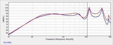
Then I've added the Semi Le to HornResp and come up with a bit of a difference in the predicted modelled response as expected.
Red manufacturers Le, blue is with Semi Le....

My only concern is that DATS thinks the VAS of the SWS15D4 is 118.5 litres, the Semi Le Calc xls says 3.12!!!???
Most likely I'm thinking I've messed up the Semi Le calc process?
XLS workbook attached.
Thanks for any help.
Looking for some guidance here please.
I'm going to build a tapped horn with a SWS15D4 using Brian's nice MTH box folder xls from diysubwoofers.org
This is what I've done...
Using DATS V2:
- Measured free air parameters - exported as txt file
- Measured Vas with added mass - exported as txt file
Using the Semi Le workbook V3 downloaded from diysubwoofers.org:
- Clicked Import 1> - Imported free air parameters txt file
- Clicked Import 2> - Imported Vas with added mass txt file
- Clicked LS-fit button with all include term check boxes ticked
- Clicked Vas Calc button a few times with different combo's of the constant check boxes ticked.
Then I've added the Semi Le to HornResp and come up with a bit of a difference in the predicted modelled response as expected.
Red manufacturers Le, blue is with Semi Le....
My only concern is that DATS thinks the VAS of the SWS15D4 is 118.5 litres, the Semi Le Calc xls says 3.12!!!???
Most likely I'm thinking I've messed up the Semi Le calc process?
XLS workbook attached.
Thanks for any help.
Attachments
Last edited:
- Home
- Loudspeakers
- Subwoofers
- Semi-Le_Calc: Calculator for Advanced Inductance Model Incorporating Semi-Inductance