Very nicely explained Circlomanen, thanks.
I know you already said that the overlaid graphs are only for understanding, but it looks like you tried to tune the Helmholtz so that the dip on the upper side could be filled, is it?
Also, do you think the Helmholtz could be tuned on the lower side of the pass band instead of the higher side?
I know you already said that the overlaid graphs are only for understanding, but it looks like you tried to tune the Helmholtz so that the dip on the upper side could be filled, is it?
Also, do you think the Helmholtz could be tuned on the lower side of the pass band instead of the higher side?


do you think the Helmholtz could be tuned on the lower side of the pass band instead of the higher side?
No. The Helmholtz resonator is a low pass filter. You don´t want to filter away most of the passband.
See the simulation above. I substantially lowered the resonant frequency (low pass cut of frequency) of the front chamber + port in the second simulation.
No. The Helmholtz resonator is a low pass filter.
Actually, A Hehlmholtz Resonator acts like a Bandpass.
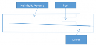
Volume of the resonator, length of port and area of port are used to tune resonant frequency and Q of the Hehlmholtz.
In a simple Bandpass Cabinet (two adjanced volumes, driver in between, one volume closed, one with a port), the portet chamber is a Hehlmholz Resonator.
I assume you already knew
")
Actually, A Hehlmholtz Resonator acts like a Bandpass
With a large and short port it will pass anything below its bandpass resonant peak - inclusive pure DC (steady airflow) without any problem. But you are right, the resonant part of the Helmholtz resonator is a bandpass function. Thanks for pointing this out.
It makes it easier to explain when viewed as a lowpass function in this design, since the port is extremely acoustically permeable below its passband.
Thanks again.
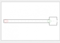
What do you think of adding a low pass filter the following way, its an attempt to low pass only the throat side of the driver.
The idea is that a normal TH is limited in bandwidth because the upper freq range is dominated by constructive/destructive interference similar to comb filtering. So, if the TH can be modified such that the throat side is low passed then interference can be avoided. The rear of the driver (mouth side) can go higher in frequency without being interfered by the throat side which is low passed now. The throat side is like a high tuned MLTL.
Attachments
Last edited:

If you balance a ROAR with an added quarter wave front section between the driver and the front resonator then you can get a very wide usable bandwidth. I have no idea how it will sound in real life, but it does look nice in Hornresp.
It is basically an 8th order ROAR15.
Attachments
Answering it as the other responsible part of the way this came to be, as Johannes pointed out it started as a bit of a joke but it got stuck, but trying to find something more straight forward and deductible as THAM (Tapped Horn Anders Martinsson) proved extremely challenging in the case of a series tuned 6'th order quarter wave design, or tapped pipe + quarter wave resonator which I feel describes it better.Would someone be so kind to write the full acronym ROAR? I try to deduce it but it is impossible for me ...
After having spent a lot of time and many notes on trying to arrange the letters describing the design in right way without having it spelling out something sounding like a medical condition I finally gave up and started approaching it in another way.
So I took Johannes surnames first to letter, RO, and I wanted the R from Resonator in there somewhere, and that is was something different, something alternative, and using the same number of letters as THAM, the result was - ROdin Alternative Resonator (...I never said it was really thought trough)
Less known fact, ROAR in Swedish means to entertain, having fun, by example:
Artisten roar publiken (The artist is entertaining the audience)
Or:
Han roar sig med att... (He's having fun doing...)
Now He's gone and added a Helmholtz resonator function to the ROAR... so where do you put the H, you won't be replacing the R that's for sure, and thank god there was not a Waveguide in his plans as well
I'll gladly hand over the task of finding a name for this one over to Johannes
"I am not done evaluating the first single driver version yet"
Are you still as enthusiastic and planning to try a 2 driver unit?
Maybe just satisfied with original 1 driver performance.
Conventional BR speakers do not work in my acoustically challenging room and I am one of those people who can instantly detect a ported speaker. If history is a guide I would need to build 2 units.
Two MCM 2421s in hand ready to go. Having said that there is no way I could tackle Hornresp to arrive at final dimensions.
Thanks.
Are you still as enthusiastic and planning to try a 2 driver unit?
Maybe just satisfied with original 1 driver performance.
I do like my single driver Helmholtz-ROAR, but I plan on building a two driver version this spring or summer.
The challange is to avoid adding complexity. I like to keep the design very simple with few parts. The single driver version is extremely easy and simple to build, with only straight sections and 90 degree cuts. I built mine alone in three hours, despite being very ill.
A symmetrical loaded two driver version does add some complexity, which is partly why I have hesitated with the build.
Cheers,
Johannes
Thanks again.
What do you think of adding a low pass filter the following way, its an attempt to low pass only the throat side of the driver.
The idea is that a normal TH is limited in bandwidth because the upper freq range is dominated by constructive/destructive interference similar to comb filtering. So, if the TH can be modified such that the throat side is low passed then interference can be avoided. The rear of the driver (mouth side) can go higher in frequency without being interfered by the throat side which is low passed now. The throat side is like a high tuned MLTL.
Hi,
You'd emailed me about how to sim this.
It's fairly straightforward, you just sim it as a tapped horn.
You have to use the newer version of Hornresp which allows for segments that don't match the previous segment. That's been around for about six months iirc.
In all other regards, it's simply a mass loaded tapped horn.


My oldest son has promised to help a friend with some nice punchy bass for his car.
Yesterday we got the driver and I started to design the layout of the Helmholtz-frontresonator ROAR.
I will post some Hornresp sims later. I am trying out Clear Linux on my main workstation and I have not yet managed to get Hornresp working in Wine. The simulation does look awful with huge peaks and dips, but this driver needs some large cross section area in the pipe to help keep velocity down. The cabingain and some DSP will help keep the power response reasonably smooth.
The large circle is where the port will be. The cone of the driver will face where I have written "HELT STAG".

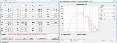
Since Hornresp can not simulate series tuned 8th order BP (yet?!) I have to work my way around this. I don´t even have reliable data on the driver and the car cabin will wreck havoc on the spl response anyway, this simulation is more of a indication of hitting the intended frequency range.
The TH1 simulation has the Helmholtz resonator chamber at the wrong place and the 8th parallel tuned BP has the 42 cm pipe section at the wrong place (and lack the tapped pipe positive feedback loop).
I guess the measured result will be somewhere between the green and red line with the uncertain TS-parameters, the cabin gain and the bass boost setting on the amp superimposed on top of it all.


Here is the same comparison with a quarter wave front resonator added. With a QW front resonator it is possible to simulate a series tuned 8th order bandpass (a tapped pipe with a long L34 pipe section connecting to the front resonator).
The Helmholtz front resonator has a slightly shorter passband, but should behave quite similarly.
- Home
- Loudspeakers
- Subwoofers
- ROAR with Helmholtz front resonator