I am working on several variations of this design, and a 4 woofer version should be quite fun and capable.

With the BP6 simulation tool in Hornresp. You can see the way I simulate in post #3 above.
Cheers,
Johannes
My apologies for not posing a clear question. I guess what I meant is "How would you model this design with 2 or 4 subwoofers and how would these simulations in Hornresp translate to an actual drawing of that design (with the 2, 4, or even 8 drivers)?" I am interested in this design and I have 2 JBL CS1214 that I am working with in Hornresp to create your design with 2 drivers. I will wait excitedly for your multi-driver models and simulations

Thanks

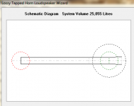
This is one reasonable simple layout of a two driver version. Much more complex then the single driver version, but it gets a more symmetrical loading of the front chamber instead, which should be a good thing. Since there is only straight non expanding sections, it should be a very simple and fast build despite the increased number of parts.
No Hornresp sim of this layout at the moment. It is a work in progress and I am not done evaluating the first single driver version yet.
with the TH function, I can't see how you would calculate s3-s4 and s4-s5
I use the 6th order BP tool in Hornresp. See my simulation in the first few posts in this thread.
I am interested in this design and I have 2 JBL CS1214
Do you have (reasonable) reliable data on those drivers?
View attachment 709847
This is one reasonable simple layout of a two driver version. Much more complex then the single driver version, but it gets a more symmetrical loading of the front chamber instead, which should be a good thing. Since there is only straight non expanding sections, it should be a very simple and fast build despite the increased number of parts.
No Hornresp sim of this layout at the moment. It is a work in progress and I am not done evaluating the first single driver version yet.
NICE. Exactly what I imagined (and that's not typical)
I think you're onto something here. Very curious if F3 is lowered a bit with 2 drivers.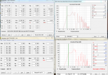

Thanks papasteack for the idea to simulate the TPBP10 as TH1 in Hornresp!
It makes it much easier to compare with actual measurements in REW.
View attachment 710022
This is how it compares with in mouth measurement indoors.
Nice car audio curve!
There is no serious acronym for ROAR. We joked around with different names and ROAR just kind of stuck with the project. I used to call it TPQWR for Tapped Pipe Quarter Wave Resonator.
Ahhh, rightly so, we all have our deductive limitations, but I was beginning to believe that my case was very serious
thank you, it has been a very important clarification for me
Do you have (reasonable) reliable data on those drivers?
Currently, I don't have any products for measuring the drivers right now other than a mic and I'm away from home at college right now anyways. Some people at AVS forum used this sub and used the TS parameters from this datasheet. https://www.hobbielektronika.hu/forum/getfile.php?id=260785
VOICE-COIL DC RESISTANCE: REVC (OHMS) . . . . . . . 3.6
VOICE-COIL INDUCTANCE @ 1 KHZ: LEVC (MH) . . . . . . . 2.57
SD (cm2) . . . . . . . 551.00
MOTOR FORCE FACTOR: BL (TM) . . . . . . . . 14.08
VAS (LITERS) . . . . . . 76.7
SUSPENSION COMPLIANCE: CMS (µM/N) . . . . 177.00
FREE-AIR RESONANCE: FS (HZ) . . . . . . . . 28.00
MECHANICAL Q: QMS . . . . . . . . . . . 8.85
ELECTRICAL Q: QES . . . . . . . . . . . 0.57
TOTAL Q: QTS . . . . . . . . . . . . 0.54
MAXIMUM EXCURSION: XMAX (IN) . . . . . . . . 0.48
XMAX (MM) . . . . . . . 12.1
I would not recommend that driver. The JBL CS1214 has a too high Qts and Vas and a way too low Bl for this kind of enclosure. It can be done, but it will sound bland and resonant, lacking a well defined and hard punch.
I would use that driver in an OB or large closed box.
That makes sense because the simulations I've done with look awful without heavy DSP filters and even then the box issues should still be audible. I bought them anyways to load one into a closed box and the other into a folded horn but I'll still probably build this anyways because I have the two drivers and an excess of scrap wood that won't be good enough to use for other projects. If the design sounds decent enough with the DSP I will just give it to one of my friends in a fraternity because they could always use a "loud sound box" where quality doesn't really matter

This is only the Helmholtz frontchamber simulated in Hornresp.
The Helmholtz frontchamber will act as high Q low pass filter, passing everything below its tuning frequency but adding its own resonant "gain" around the tuning frequency (upper part of the passband). The lower tuning frequency is from the tapped pipe that encircles and ends in the Helmholtz resonant chamber.
This simplified Hornresp simulation is not correct since the tapped pipe and the Helmholtz front chamber couples tightly to each other - which is not shown here.

Both curved overlaid. This is not really the correct way to simulate since the tapped pipe and the Helmholtz frontchamber couple to and effect each other.
I made this simplified Hornresp simulation just to try to show the contribution of the two different parts in a more clear and distinguishable way.
- Home
- Loudspeakers
- Subwoofers
- ROAR with Helmholtz front resonator