For a low-Qts driver in a dipole system, I'd say it looks about right.
The grey trace is effectively the infinite baffle output - you're only considering the sound from the front of the cone, and the Hornresp inputs show basically no loading on the cone.
I suspect simulating a very large sealed box would be very similar to the grey trace, except for the bump around 180Hz.
Chris
No problem. It took me a little while to figure out - Hornresp sims for dipoles never lined up with what I was hearing, until I realised the default "power response" was the sum of the outputs over all angles. With a dipole system, half of the bass is out of phase with the other half, so most of it cancels, as seen in the sims.
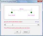
Introducing the path length lets you do it properly, although it's difficult to decide exactly what the path length should be:
1 - Distance front-to-back of the H-frame. Sort-of works, but it assumes all the output is at the very edge of the waveguide, when actually the pressure waves fill the entire cavity
2 - centre of cavity exit at the rear to centre of the front. That'd add the width of the H-frame to the path length, but assumes you're effectively firing all the sound from a single point in the middle of the cavity exit, which isn't true either.
I'd probably go for a compromise - path length = length of H-frame plus half of the width.
That suggests the output is, on average, half-way between the edge of the H-frame cavity and the centre. Probably close enough for our purposes.
It's possible to figure it out empirically, but it'd be a lot of work when I suspect the equation I've set out above will be pretty darn close.
Chris
input the path length difference. In this case, it'll be the distance from the front to the back of the H-frame, plus half the width.....
Chris
Thanks for the Hornresp help which I really need. Ive never tried Hornresp before and it looks complex.
I wonder about the best estimation of the path length difference for the H Frame? If it possible in Hornresp to select a point in space for the measurements to be simulated eg 5m in front of the H-baffle to represent the listening position?
From a point in front of the H-frame I assume the path difference (Pd) would be 2D where D=total depth of the H-frame plus the "effective length" adjustment for the end factor. Thats defined by Martin J. King (Page 3) as 0.6r where r is the radius of a circle of equivalent area of the H-baffle mouth. That seems to be for the entire H-frame:
Pd = 2D + 1.2sqroot (x.y/pi)
Where have I gone wrong?

Last edited:
Hornresp only allows you to input a path length difference, I'm afraid.
The diagrams above don't include the width (in the sketch, height) of the H-fram contributing to the path length difference, even though the line follows that path.
When we're talking about 18" drivers (ie, the baffle will be around 20" square), the additional 10" path length on a H-frame that might be 20" deep is non-trivial, and should be added.
Chris
I use PRECISION DEVICES PD.2150 21” 1000 WATT Loudspeaker 8ohm for my drivers.
If you are using this setup in an enclosed space, use just ONE or if you must have TWO place them together anywhere in the room to avoid audio cancelling or holes in the bass as you walk around. Human ears cannot determine where sub sound comes from, so in a corner, out of the way is ideal. Your selected speakers are only 92.8dB/metre, whereas the 21" is much more sensitive at 98dB/metre. Less power required for more sound.
How did you load the PD2150? I have used them in a large vented enclosure and a small sealed, but with plenty of EQ.
I have never used them in an OB system, they will need loads of EQ to get decent bass extension.
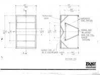
They fit snugly into a folded 'W' bin. 24"W x 28"D x 36"H. You face the speaker at the rear sheet of 1" Birch Pine mounted in the 'W'. Standard design by Gauss Loudspeakers, circa 1970. Taken on board by many manufacturers.
Here is an example used for 15" speakers, just increase the size BUT it is important to use hardwood ply.
Here is an example used for 15" speakers, just increase the size BUT it is important to use hardwood ply.
Attachments
Does horn response take into account the increased air load on the driver? When building a "deep" H-frame, the frame helps to add air load to the driver compared to infinite baffle conditions (e.g. those used for MFG TS parameter measurement). Qts will be higher, Fs lower, and sensitivity slightly lower.
There is a good description of this in Martin King's paper comparing the same driver in a planar OB, U-frame, and H-frame. There were notable differences in the TS parameters even for his not-all-that-deep H-frame.
There is a good description of this in Martin King's paper comparing the same driver in a planar OB, U-frame, and H-frame. There were notable differences in the TS parameters even for his not-all-that-deep H-frame.
Also: if you make the H-frame deeper the dipole peak (the main peak in the response) will move down in frequency but you will also have less loss at the lowest frequencies AND will increase the total air load on the driver. At the same time you might want to make the H-frame opening larger (e.g. make the H-frame taller and wider). This will reduce the Q of the dipole peak.
I am currently building a 30"H x 30"W x 45"D H-frame for this driver to see how that works. It will be operated from 80Hz and down, just where the response is turning down from the dipole peak.
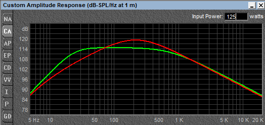
Unless you want to use the driver up to 180Hz or so like your plots show, you can also increase the depth of the frame so that the peak is located about where you want to cross over.
After you build it, measure the response and then add a LOW-PASS filter of 6 or 12dB/oct with its corner at a low frequency like 30-40Hz. This will largely flatten out the rising response. On top of that you can use EQ to further flatten the response since neither 6dB/oct nor 12dB/oct will be a perfect fit.
I am currently building a 30"H x 30"W x 45"D H-frame for this driver to see how that works. It will be operated from 80Hz and down, just where the response is turning down from the dipole peak.
Unless you want to use the driver up to 180Hz or so like your plots show, you can also increase the depth of the frame so that the peak is located about where you want to cross over.
After you build it, measure the response and then add a LOW-PASS filter of 6 or 12dB/oct with its corner at a low frequency like 30-40Hz. This will largely flatten out the rising response. On top of that you can use EQ to further flatten the response since neither 6dB/oct nor 12dB/oct will be a perfect fit.
Does horn response take into account the increased air load on the driver? When building a "deep" H-frame, the frame helps to add air load to the driver compared to infinite baffle conditions (e.g. those used for MFG TS parameter measurement). Qts will be higher, Fs lower, and sensitivity slightly lower.
There is a good description of this in Martin King's paper comparing the same driver in a planar OB, U-frame, and H-frame. There were notable differences in the TS parameters even for his not-all-that-deep H-frame.
I believe it does, yes.
Although to be a little pedantic, the driver's T/S parameters aren't changing - it's what happens when you load them into the cabinet.
You can double-check by comparing a H-frame simulation with an infinite (or open) baffle - the impedance peak should be lower in frequency.
Chris
Thats good to know, thanks. Now I'm really keen to use Hornresp. Is there a guide for getting Hornresp to model an H-frame for dummies?
I bumble around in Hornresp but cant find where to load the path difference. Read the guide and searched the net and still stuck. I played around with the Hornresp wizard until I got an H-baffle shape using the setting below. Played in the Tools but still couldn't find the path difference box.
I bumble around in Hornresp but cant find where to load the path difference. Read the guide and searched the net and still stuck. I played around with the Hornresp wizard until I got an H-baffle shape using the setting below. Played in the Tools but still couldn't find the path difference box.
Attachments
Last edited:
Played in the Tools but still couldn't find the path difference box.
After calculating the acoustical power response, select Tools > Output > Combined.
Also see this post:
http://www.diyaudio.com/forums/subwoofers/119854-hornresp-833.html#post5452029
Attachments
Last edited:
Hi Everyone. The Dipole18's were mentioned so I figured it would be good to give some info here based on design goals and real world measurements.
First when it comes to open baffles whether it is a flat baffle, U, or H, there are two factors that come into play with the rolloff. The baffle rolloff and the driver rolloff. The baffle rolloff will be the same regardless of what driver goes in the baffle, so lets look at the driver rolloff first. We will look at an infinite baffle, not an open baffle so we are looking only at driver response. We will use that PD.2150 as a comparison to the Dipole18. The Dipole18 has an optimal Q of .80, chosen specifically to get the lowest possible F3 point without getting too boomy and losing control. The suspension of the Dipole18 is also very soft so it is not contributing much to the rolloff. The PD.2150 has a much stiffer suspension and much lower Qts. The difference is quite huge. At 23hz, the Dipole18(green) is at -3dB while the the PD.2150 (red) is at -14dB at the same frequency.
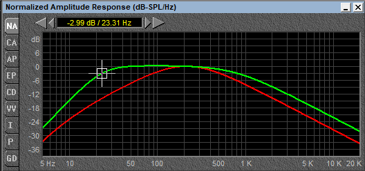
This is just telling us the shape of the curve though. What happens when we see what the output is based on power input? The Dipole18 has 15mm klippel verified Xmax. The PD.2150 has 10.5mm Xmax. When the Sd of both drivers is compared, the Dipole18 displaces 3.65L p-p at 30mm-p-p excursion. The PD.2150 displaces 3.55L at 21mm p-p excursion. For all practical purposes they can move the same amount of air and have about the same max output levels.
The huge difference is the amount of power it takes to get there. The soft suspension and optimal Qts of the Dipole18 allows it to be very "bass efficient". Meaning that it moves to high excursions with very small input power. At 23hz, to move the Dipole18 to the full 15mm Xmax requires 125W input. The PD.2150 produces 6dB less input. It requires a full 500W to get to the same level that the Dipole18 produces with 125W at 23hz. This is counter to most intuition. People see a high efficiency rating on a driver and assume it will be that way across the board. As you can see, the lower efficient Dipole18 is actually far more efficient at low frequencies. Some people also question why the Dipole woofers have lower power ratings. They simply don't need to have higher power ratings when the full excursion and full output potential is achieved every time with less than the rated power. They are typically expected to be used in multiples as well so it is very common to be able to use 2-4 per channel with modest power amplifiers while other drivers may require massive pro amplifiers to be used.
In addition to that, factor in the distortion characteristics. In open baffles, woofer are required to work at higher excursions than boxed woofers to make up for baffle rolloff. The Dipole18 was intentionally designed a massive underhung motor. There is nearly perfect BL linearity everywhere within the +/-15mm Xmax. The Dipole12 BL curve here is the same as the Dipole18. You can see the improved sample B on the right, while both are nearly ruler flat within this 30mm range. This means equal force throughout the 30mm stroke and consistent parameters within that range. It will sound the same at high and low volume levels.
The PD.2150 has a 30mm long coil in a 15mm gap which will provide a typical bell shaped BL curve. At the rated 10.5mm Xmax, Bl is already dropped by 30%. This means parameters drastically change by that point and it will sound different as volume levels are increased.
In addition to this, Dipole18 have the Full Copper Faraday Sleeve used on every one of our drivers. This reduces inductance to a tiny amount, linearizes inductance, and eliminates flux modulation. Distortion is drastically reduced, especially 3rd harmonic distortion which is the most audible.
That all said, what happens in the real world once a Dipole18 is put on a baffle? We did a lot of testing with the Dipole18 in a U-baffle that was 22x22x14" deep. Simulations are good, but measured results are important.
One thing to note is that positioning is very important. We measured close mic response which you can see in the upper two elevated curves. One with just a completely open baffle. Another with heavily stuffed rear volume. The black curve approximates the model quite well.
The other curves were measured at the listening position about 2.5m from the baffle. As the distance from the rear wall is increased, the lower end continues to tip up. The rear wave comes out, hits the wall, and comes back forward where it either sums or cancels with the front wave. As distance is increased, the summation is pushed lower in frequency and the bottom end increases. You have to be careful though depending on how high you want to use them. With more distance, the response begins to get more rough between 100-200hz. At 3ft away, response is +/-3dB from 150hz down to about 30hz. At 4ft from the wall, response is +/-3dB from 125hz down to about 24hz. This is with no EQ applied to correct the bottom end. Build it. Place it 3-4 ft out from the wall. Lowpass at 100hz or so, and no further correction to response should be needed.
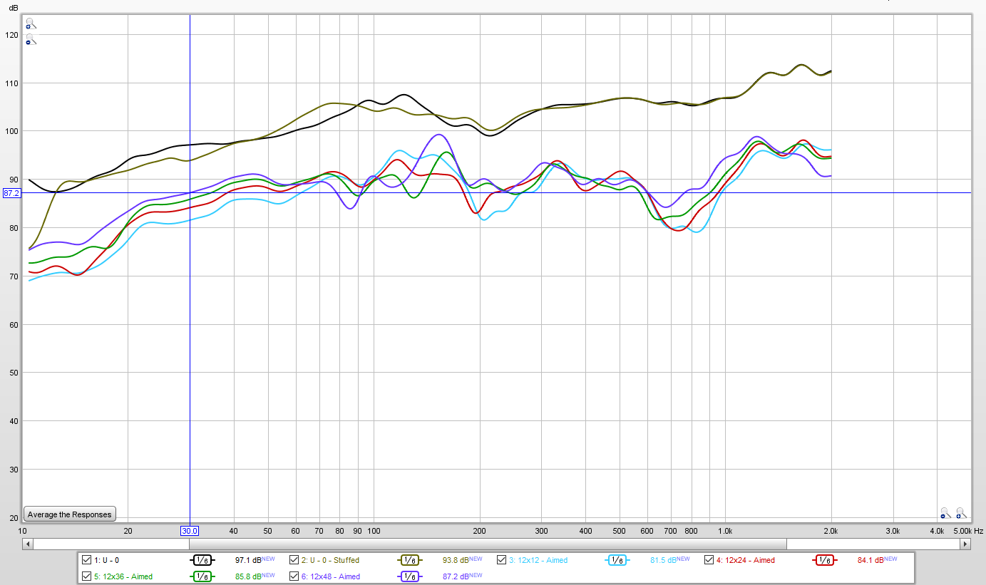
Now if we go back to the comparisons with the PD.2150, remember that it was 11dB more down at 23hz than the Dipole18. This also applies in a U-baffle this size. Where the Dipole18 is +/-3dB down to 24hz, the PD.2150 would require 11dB of EQ and 4x the power to tilt the low end response and get the same curve shape.
Again this is not to pick on or call fault to the PD.2150. It is a good driver for the intended application of live sound reinforcement in large vented boxes. There is a huge difference between a good driver being put in an open baffle application and a fully optimized driver designed specifically for the application.
John
First when it comes to open baffles whether it is a flat baffle, U, or H, there are two factors that come into play with the rolloff. The baffle rolloff and the driver rolloff. The baffle rolloff will be the same regardless of what driver goes in the baffle, so lets look at the driver rolloff first. We will look at an infinite baffle, not an open baffle so we are looking only at driver response. We will use that PD.2150 as a comparison to the Dipole18. The Dipole18 has an optimal Q of .80, chosen specifically to get the lowest possible F3 point without getting too boomy and losing control. The suspension of the Dipole18 is also very soft so it is not contributing much to the rolloff. The PD.2150 has a much stiffer suspension and much lower Qts. The difference is quite huge. At 23hz, the Dipole18(green) is at -3dB while the the PD.2150 (red) is at -14dB at the same frequency.
This is just telling us the shape of the curve though. What happens when we see what the output is based on power input? The Dipole18 has 15mm klippel verified Xmax. The PD.2150 has 10.5mm Xmax. When the Sd of both drivers is compared, the Dipole18 displaces 3.65L p-p at 30mm-p-p excursion. The PD.2150 displaces 3.55L at 21mm p-p excursion. For all practical purposes they can move the same amount of air and have about the same max output levels.
The huge difference is the amount of power it takes to get there. The soft suspension and optimal Qts of the Dipole18 allows it to be very "bass efficient". Meaning that it moves to high excursions with very small input power. At 23hz, to move the Dipole18 to the full 15mm Xmax requires 125W input. The PD.2150 produces 6dB less input. It requires a full 500W to get to the same level that the Dipole18 produces with 125W at 23hz. This is counter to most intuition. People see a high efficiency rating on a driver and assume it will be that way across the board. As you can see, the lower efficient Dipole18 is actually far more efficient at low frequencies. Some people also question why the Dipole woofers have lower power ratings. They simply don't need to have higher power ratings when the full excursion and full output potential is achieved every time with less than the rated power. They are typically expected to be used in multiples as well so it is very common to be able to use 2-4 per channel with modest power amplifiers while other drivers may require massive pro amplifiers to be used.
In addition to that, factor in the distortion characteristics. In open baffles, woofer are required to work at higher excursions than boxed woofers to make up for baffle rolloff. The Dipole18 was intentionally designed a massive underhung motor. There is nearly perfect BL linearity everywhere within the +/-15mm Xmax. The Dipole12 BL curve here is the same as the Dipole18. You can see the improved sample B on the right, while both are nearly ruler flat within this 30mm range. This means equal force throughout the 30mm stroke and consistent parameters within that range. It will sound the same at high and low volume levels.
The PD.2150 has a 30mm long coil in a 15mm gap which will provide a typical bell shaped BL curve. At the rated 10.5mm Xmax, Bl is already dropped by 30%. This means parameters drastically change by that point and it will sound different as volume levels are increased.
In addition to this, Dipole18 have the Full Copper Faraday Sleeve used on every one of our drivers. This reduces inductance to a tiny amount, linearizes inductance, and eliminates flux modulation. Distortion is drastically reduced, especially 3rd harmonic distortion which is the most audible.
That all said, what happens in the real world once a Dipole18 is put on a baffle? We did a lot of testing with the Dipole18 in a U-baffle that was 22x22x14" deep. Simulations are good, but measured results are important.
One thing to note is that positioning is very important. We measured close mic response which you can see in the upper two elevated curves. One with just a completely open baffle. Another with heavily stuffed rear volume. The black curve approximates the model quite well.
The other curves were measured at the listening position about 2.5m from the baffle. As the distance from the rear wall is increased, the lower end continues to tip up. The rear wave comes out, hits the wall, and comes back forward where it either sums or cancels with the front wave. As distance is increased, the summation is pushed lower in frequency and the bottom end increases. You have to be careful though depending on how high you want to use them. With more distance, the response begins to get more rough between 100-200hz. At 3ft away, response is +/-3dB from 150hz down to about 30hz. At 4ft from the wall, response is +/-3dB from 125hz down to about 24hz. This is with no EQ applied to correct the bottom end. Build it. Place it 3-4 ft out from the wall. Lowpass at 100hz or so, and no further correction to response should be needed.
Now if we go back to the comparisons with the PD.2150, remember that it was 11dB more down at 23hz than the Dipole18. This also applies in a U-baffle this size. Where the Dipole18 is +/-3dB down to 24hz, the PD.2150 would require 11dB of EQ and 4x the power to tilt the low end response and get the same curve shape.
Again this is not to pick on or call fault to the PD.2150. It is a good driver for the intended application of live sound reinforcement in large vented boxes. There is a huge difference between a good driver being put in an open baffle application and a fully optimized driver designed specifically for the application.
John
Just thought I would throw this in also. This are not the Dipole18 but the Dipole15's. There is however not much difference in using more 15" compared to less 18" drivers. The main consideration is getting the displacement needed to achieve the levels desired. Building the U-baffles in a modular approach allows to add more as time goes on if you need more output. Some start with 2 and add 2 more later on. Others start with 4 and go up to 8 at a later date.
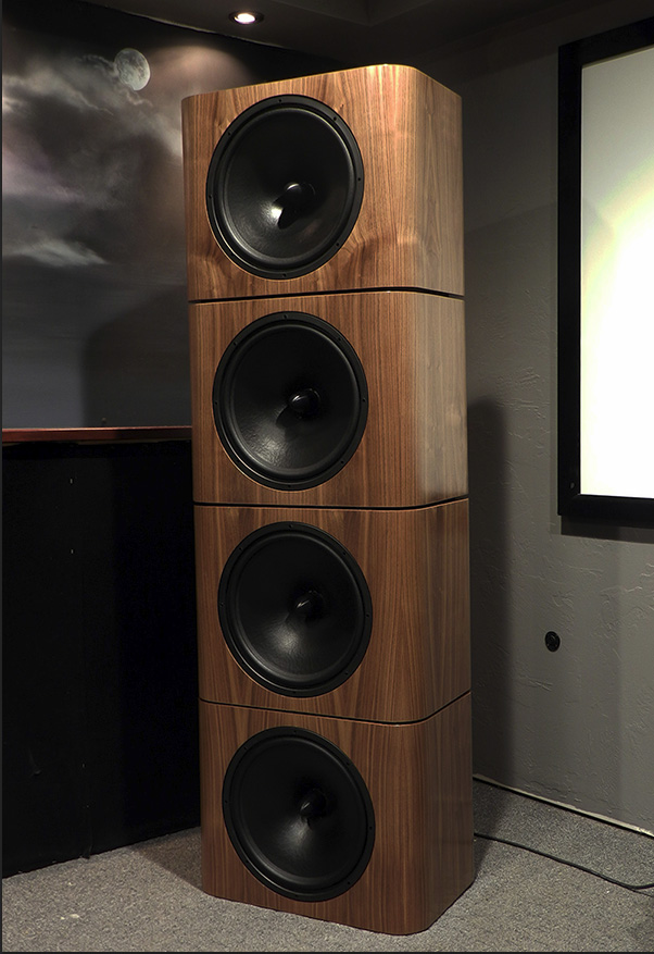
These ended up going into a system where they were flat down to 22hz and used up to about 500hz where they were crossed to a large horn. The Dipole woofers also have much wider bandwidth and can do more than just subwoofer duty.
John
These ended up going into a system where they were flat down to 22hz and used up to about 500hz where they were crossed to a large horn. The Dipole woofers also have much wider bandwidth and can do more than just subwoofer duty.
John
Hi John
Those U-baffles look great with the matching wood grain.
Thanks for posting the Dipole -18 measurements. Whats going on with the good low end response down to 30Hz? OB are meant to need massive low frequency boost equalisation but you seem to indicate there's no boost at all used in those measurements. Is that correct?
Hi John
Those U-baffles look great with the matching wood grain.
Thanks for posting the Dipole -18 measurements. Whats going on with the good low end response down to 30Hz? OB are meant to need massive low frequency boost equalisation but you seem to indicate there's no boost at all used in those measurements. Is that correct?
It was not as I expected at first either but again there are two different things to look at. Baffle and driver rolloff. Most open baffles have very little low end output because the driver contributes another 10dB to the rolloff. The optimal Q and soft suspension eliminates this issue.
If you look at a model of the Dipole18 in this U baffle it approximates the black curve you see up top. This does show about an 11dB drop from 100hz to about 30hz. If you put this open baffle outside it will measure very close to that. However, as with any subwoofer there is some room gain and corner boundary gain that adds to the low end. When you put it in the room with adequate space behind it, the rear wave comes off the wall behind and comes back in phase with the front wave. This provides a significant gain at the listening position. In this case, I used no EQ with the Dipole18 in this open baffle.
If you were to put the PD2150 all the same room factors would come into play in the same U-baffle with no EQ. However, due to the driver rolloff, it would be 11dB further down at 23hz than the Dipole18. You would need EQ then for sure.
Martin King has some good info up when he used the Dipole15's. You can see in his models there is a good amount of gain that happens over what is predicted.
Project 10 : Lowther Open Baffle / Acoustic Elegance H Frame System
Hi all, just came by and want to know what W and H stands for, in the very first post.
Another question is if it's normal for a $319 woofer that I don't find any measurements about it on the manufacturer's page, no impedance curve, no freq. curve, to mention the 2 most important at least ? Acoustic Elegance Dipole10 woofer for Open Baffle Applications
Another question is if it's normal for a $319 woofer that I don't find any measurements about it on the manufacturer's page, no impedance curve, no freq. curve, to mention the 2 most important at least ? Acoustic Elegance Dipole10 woofer for Open Baffle Applications
Also: if you make the H-frame deeper the dipole peak (the main peak in the response) will move down in frequency but you will also have less loss at the lowest frequencies AND will increase the total air load on the driver. At the same time you might want to make the H-frame opening larger (e.g. make the H-frame taller and wider). This will reduce the Q of the dipole peak.
I am currently building a 30"H x 30"W x 45"D H-frame for this driver to see how that works. It will be operated from 80Hz and down, just where the response is turning down from the dipole peak.
Unless you want to use the driver up to 180Hz or so like your plots show, you can also increase the depth of the frame so that the peak is located about where you want to cross over.
After you build it, measure the response and then add a LOW-PASS filter of 6 or 12dB/oct with its corner at a low frequency like 30-40Hz. This will largely flatten out the rising response. On top of that you can use EQ to further flatten the response since neither 6dB/oct nor 12dB/oct will be a perfect fit.
Hi, I know that it is a two year late question but did you finally get some good results with that Faital 18XL1800 in that H-frame or any other OBconfiguration? Thank you!
- Status
- This old topic is closed. If you want to reopen this topic, contact a moderator using the "Report Post" button.
- Home
- Loudspeakers
- Subwoofers
- Suitable 18" or 21" Bass Drivers to construct a W or H stereo pair of subwoofers.