Your image does not show… attach it to a post.
dave
I did attach it to the post. I can see it. Let me see if I can find another one.
Thanks for the info.
EDIT:
Here's an example of what I'm asking about:

Last edited:
So, I read through all of Martin King's scholarly breakdown, on how he derived his conclusions. I half glanced through a pile of messy differential equations. He even made a nice reference to Maple V software. (which is used to do symbolic math - very nice) However, I'm not sure that I really got down to the heart of the matter of what the actual final product looks like.
He seems to have done most of his testing on a straight box, with variances approaching terminus. (flared and tapered) He seems to be saying that a tapered design is the best, but trickiest to get right. And then, his website states that his design software hasn't been available to new users since 2014, with restricted access to existing users.
I like his work. He's meticulous, and he really did a deep dive into the subject matter. But how can I put it into practice?
I would not characterize the cabinet shown as a "transmission line", but rather as a bass reflex type, with a very small cabinet and a very long reflex tube... I doubt you would be happy with the results if you model it.
Ok, I get that - it was just an example. But what I am asking is whether or not it's possible to optimize that type of design, according to the T/L design parameters.
In other words... If I were to create the proper size and length opening, would it fit the design intent of the T/L? Or is there some other fundamental difference?
The picture shown is called a horn by the manufacturers, but is a mess. It is designed like an air cavity/end loaded horn, but acts like an undamped TL/quarter wave resonator. For a typical 3” driver will be way longer than practical, the smooth curves make the ripple caused by unwanted harmonics worse — squared off corners act as additional LP filters. It also uses translam construction, pretty shape, but a waste of material, and the "pretty” brings no sonic benefit. Further it is MDF which is not the best material for building
speakers.
One does not even have to look at the math to get what is needed out of Martin’s papers.
dave
speakers.
One does not even have to look at the math to get what is needed out of Martin’s papers.
dave
Ok, I get that - it was just an example. But what I am asking is whether or not it's possible to optimize that type of design, according to the T/L design parameters.
Yes, with a TL modeller. One puts the driver into a box and plays. It takes a lot of that. Successful TL design takes a lot of playing, fortunately the modelers mean you don;t actually have to build boxes. You can get a lot of clues from those that have some expertise and take things like taper. driver offset, and restricted terminus from what Martin has written and that many of us have practically shown by building boxes based on his and others TL modelers.
dave
I have been modeling a folded labyrinth, like the one shown, using the parameters from Keith Webb's spreadsheet at Transmission Line Theory.
I selected the 10" Dayton woofer that was mentioned earlier, as well as the 8" version of it. (I'm modeling both in a CAD program, as I'm interpreting the data)
The only thing that I'm not really sure about, is how much of the total volume is the line, vs the driver chamber.
How do I figure driver offset? I'm not sure that I'm seeing that - or if I am, I'm not recognizing it. (in the spreadsheet)
The optimum offset is determined by playing with the software. In the basic TLs that the tables & the SS calculate that optimum offset has been figured out for you. It is a table that gives the offset as a farction of the line length from th etop of the box that is based on the taper.
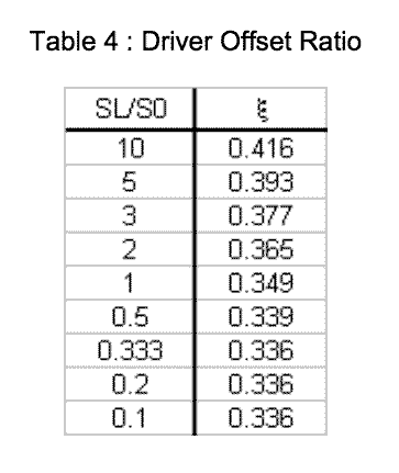
You need to have read & use the table article to take full advantage of the SS. On 1st glance it looks like the term Dz (in the SS) is used for the offset, but the number doesn’t quite jive with the table, perhaps further optimization since the tables article.
dave
You need to have read & use the table article to take full advantage of the SS. On 1st glance it looks like the term Dz (in the SS) is used for the offset, but the number doesn’t quite jive with the table, perhaps further optimization since the tables article.
dave
Attachments

Augspurger covers off a bit different set of examples, including the prechamber (also seen in Radfords & IMFs). They can be modeled in any of the modelers including the 2 currently available for Windoz guys (HornResp, and Leonard Software’s, both free with extensive threads here).
Of interest is that one will get different results depending on whether the line comes off the back of the pre-chamber or the front (relative to driver placement, all related to the driver offset)
Augspurger's paper(s) are worth reading for more insight, the Speaker Builder ones are expanded vis-a-vis the AES paper.
That both MJK and Augspurgers models came out at the same time, and that the mechanical (MJK) and electrical analogs gave essentially the same results was a big check mark for theri validity. Martin kept exploring and making new findings, Augspurger;s became stagnant as he went off to do other things.
dave
I'm not seeing this software. Planet10, what is that table from?
It is from the paper that the spreadsheet is derived from… on the same page you would have downloaded the software from… Has the word table in it.
dave
I got mine from here: Transmission Line Theory
It is titled, "Alignment Tables Spreadsheet by Keith Webb (Excel 3/03/09)". However, I don't see any Offset section. There are 3 tabs at the bottom - one is "Print Here", and the other is "Empty Page"
It is titled, "Alignment Tables Spreadsheet by Keith Webb (Excel 3/03/09)". However, I don't see any Offset section. There are 3 tabs at the bottom - one is "Print Here", and the other is "Empty Page"
But there is a Dz cell. You cannot really use the spreadsheet without reading the pdf from which the software is derived, the link before the SS called "Classic Transmission Line Alignment Tables”. Most of the meat in Matrin’d work is in the pdfs… you need to download them and read them.
dave
dave
Already have them, have been reading them... I'll go back and give it a second look.
Note that the ideal offset for the driver will also change depending on how much stuffing (if any) you use in the TL, and where that stuffing is located. Really, this is job for software that can sim the TL, like Hornresp.
- Status
- This old topic is closed. If you want to reopen this topic, contact a moderator using the "Report Post" button.
- Home
- Loudspeakers
- Subwoofers
- Want to build a TL subwoofer - driver advice needed