Hello folks,
the pair of 1984 B&M Omega I own already employs electret Microphone feedback for Bass servo control. After all this construction is old and I'm now wondering how I could/may be able to optimise the very simple servo circuit as it does not accomodate for any adjustments.
A little background:
I'm not really sure if the above solution as such is "state of the art", accomodating for all the possib le or necessary servo optimizations, i.e. can achieve what is possible. Therefore would like to gather input for servo bass improvement of my speakers, including how I would confirm by (acoustic and oscilloscope) measurements.
Sincere thanks for the inputs, recommendations and discussion!
Regards,
Winfried
the pair of 1984 B&M Omega I own already employs electret Microphone feedback for Bass servo control. After all this construction is old and I'm now wondering how I could/may be able to optimise the very simple servo circuit as it does not accomodate for any adjustments.
A little background:
- 2x 200mm Bassdrivers
- Each driver runs in its own, closed volume
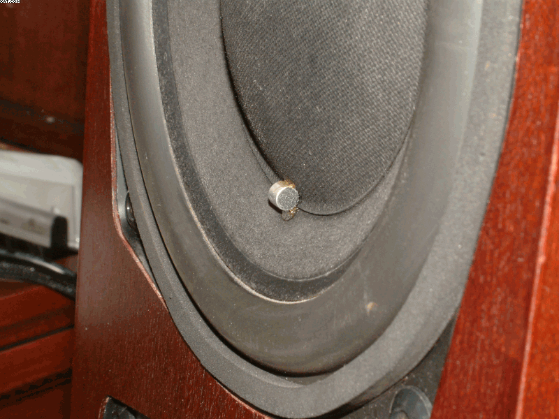
- A Microphone is glued onto each driver cone surface
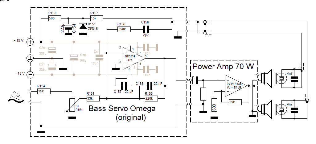
- Bandwidth: ~ 30 Hz (achieved by servo) - 180 Hz (by 4th Order LR Low-Pass)
- One 70 W Poweramp drives Bass chassis (parallel)
I'm not really sure if the above solution as such is "state of the art", accomodating for all the possib le or necessary servo optimizations, i.e. can achieve what is possible. Therefore would like to gather input for servo bass improvement of my speakers, including how I would confirm by (acoustic and oscilloscope) measurements.
Sincere thanks for the inputs, recommendations and discussion!
Regards,
Winfried
Attachments

Hello Ben,
and thanks for being the first respondent. So much I can say:

The feedback circuit senses and "compensates" for the driver resonance caused frequency and phase response as well as other non-linearities, i.e. linearises sound pressure frequency response and lowers distortion. Yes, all this within given power, excursion and so on limits. The integrator effectively extends the sound reproduction of the bassbox to a selectable lower bass cut off, defined by the integrator C and the Resistor "bridging" it.
I have not yet tried the cicuit open-loop, may have to do this to find if it still works") .
.
There are a few details I don't understand about the circuit myself, though, e.g. what is the function of the 4n7 C across the microphone terminals in the actual circuit?
Hoping this helps,
Winfried
and thanks for being the first respondent. So much I can say:
- The circuit has been implemented in 1984 and has worked ever since
- The Mic is a Mic and senses the sound pressure level while being fastened to the piston and moves with the piston
- The Mic membrane itself is rotated 90° vs. the piston movement direction, this way it does not (or just minimally) pick up mechanical acceleration.
- The sensed sound pressure is fed back as electrical Mic signal and is compared with / subtracted from the incoming electrical audio signal
- Differences are this way sensed and corrected "real time": A closed feedback loop.
The feedback circuit senses and "compensates" for the driver resonance caused frequency and phase response as well as other non-linearities, i.e. linearises sound pressure frequency response and lowers distortion. Yes, all this within given power, excursion and so on limits. The integrator effectively extends the sound reproduction of the bassbox to a selectable lower bass cut off, defined by the integrator C and the Resistor "bridging" it.
I have not yet tried the cicuit open-loop, may have to do this to find if it still works
.There are a few details I don't understand about the circuit myself, though, e.g. what is the function of the 4n7 C across the microphone terminals in the actual circuit?
Hoping this helps,
Winfried
Attachments

A simple MF solution. Far harder to use MF as you go up the tone scale. So possibly this system is meant to handle the main task, tightening up the resonance. The capacitor might be there to cancel the mic feedback north of the resonance band.
Using the figure-8 reception of that mic (once I paid 50-cents for that kind of capsule), if it works as you suggest (which still seems unlikely to me from where I sit), is a clever concept but pretty crude.
Odd not to simply use a glued-on device as an accelerometer, like a piezo crystal?
It would be really great if you posted REW FR, HD, and impulse-related curves before and after the motional feedback loop was connected.
B.
Last edited:
Hi Ben,
Regards,
Winfried
Yes, that may well be the case. Maybe I find out later......The capacitor might be there to cancel the mic feedback north of the resonance band...
Well, we could discuss if you would elaborate on your explicit concerns. The geniality of this approach may be in the simple, though... And if a more elaborate feedback loop circuit (which takes more, which ever, considerations into account) would be an improvement, what I'm after here would be achieved....Using the figure-8 reception of that mic (once I paid 50-cents for that kind of capsule), if it works as you suggest (which still seems unlikely to me from where I sit), is a clever concept but pretty crude...
Simple answer: Accelerometer feedback control for speakers was a patent by Philips in those days, so not usable commercially for Backes & Mueller. Using the accelerometer feedback, by the way, has it's own set of limitations and complications....Odd not to simply use a glued-on device as an accelerometer, like a piezo crystal?...
I'm planning that, have to see when I get the chance for measurements....It would be really great if you posted REW FR, HD, and impulse-related curves before and after the motional feedback loop was connected.
Regards,
Winfried
Last edited:
All good. Thanks.
For anything in audio and esp. motional feedback, many trivially different patents introduced for commercial reasons. For example, ACE-BASS texts are hocus-pocus. Likewise, there may be differences between the manufacturer's write-up on your device and how you would describe it in reality.
Great to see your before-and-after REW results, esp. if you can link to your entire REW data file, not just the pretty pictures.
B.
Winfried,There are a few details I don't understand about the circuit myself, though, e.g. what is the function of the 4n7 C across the microphone terminals in the actual circuit?
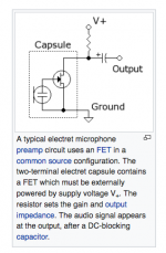
The capacitor is used to filter the electret microphone (typically omnidirectional) DC power supply voltage out of the audio path.
Art
Attachments
The capacitor is used to filter the electret microphone DC power supply voltage out of the audio path
Not the 4n7. One of us needs to take Electricity 101 again or buy new eyeglasses; not certain which or who.
I'll stick with my loop attenuation guess. Or possibly RF filter.
B.
Opthamologist appointment scheduled for 4/19/18, maybe I should schedule it sooner ;^)...Not the 4n7. One of us needs to take Electricity 101 again or buy new eyeglasses; not certain which or who.
I'll stick with my loop attenuation guess. Or possibly RF filter.
B.
Never mind folks! I'm glad the misunderstanding got resolved.
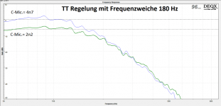
I follow the RF blocking theory to a good extent, but the 4n7 is mylar (not ceramic) and past measurements had shown that it does have an effect on low pass roll-off: Because of an appearent dip around the 180 Hz cross over region I had tried 2n2 to reduce that, which worked, but lost ~6dB woofer output level. ... one of the reasons I'm looking for other/better optimization alternatives
Maybe a possible trick here would be to filter the Mic-signal with a low pass equivalent to the 180 Hz cross-over low-pass, so the feedback circuit does not "hear" the mid-driver taking over at 180 Hz? Would that be "a huge overkill" or wrong or counterproductive or a potential improvement?
Cheers,
Winfried
Attachments
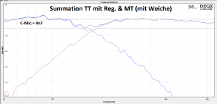
The mic works with the inverse-distance law, each doubling of distance looses 6 dB level. At "ground zero" the woofer level is likely far louder at the acoustic crossover than the relatively distant mid-driver. If you lower the mic low pass, it won't "hear" harmonic distortion as well, so can't correct it as effectively.Maybe a possible trick here would be to filter the Mic-signal with a low pass equivalent to the 180 Hz cross-over low-pass, so the feedback circuit does not "hear" the mid-driver taking over at 180 Hz? Would that be "a huge overkill" or wrong or counterproductive or a potential improvement?
The 4n7 is clearly operating in the audio range. As you enlarge the operating band, you risk entering a zone of instability. Manufacturers of motional feedback systems live in fear of instability and blown drivers: otherwise they would have gone to a smaller filter cap too. Not saying what a DIYer should do with a closely monitored home system, just want to be careful.
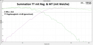
This may sound heretical, but multi-speaker FR charts can be misleading due to phase/interference effects and in relation to the REW mic and musical content. In other words, pure swept sine wave results may not correspond to the audible loudness on complex sounds. So the middle FR with the dip may sound better than the 2n2 on the right.
B.
That kind of electret mic has omnidirectional (kugel) characteristic.Using the figure-8 reception of that mic (once I paid 50-cents for that kind of capsule),
… not really sure if the above solution as such is "state of the art", accommodating for all the possible or necessary servo optimizations, i.e. can achieve what is possible. Therefore would like to gather input for servo bass improvement of my speakers, including how I would confirm by (acoustic and oscilloscope) measurements.
Looks like you have an interesting speaker in your hands
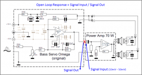
To determine what B&M achieved in the circuit and what optimization is possible, you would need to measure the open loop response. To do this, you need to break the feedback loop. The most convenient place to do this is the connection between the preamp and power amp as shown in the attached figure by the red X. Input a low level test signal into the power amp(10 – 50mVrms) from measurement software(ARTA, REW, etc) and measure the electrical frequency/phase response coming out of the preamp where you broke the loop. Dividing this by the input signal will gives the open loop response, which tells you how much feedback is being used and what the gain and phase margin is.
While you have the feedback loop broken, you might also measure the acoustic output of woofers while using the same direct input into the power amp. This will show you what the natural response of the woofer/cabinet is before feedback is applied.
The 4n7 capacitors across the microphones form a first order low pass filter with R157, rolling off the feedback signal above about 1kHz.…There are a few details I don't understand about the circuit myself, though, e.g. what is the function of the 4n7 C across the microphone terminals in the actual circuit?
You mention seeing a 6dB change in woofer level when changing the values of these capacitors. I don’t understand why that would be unless one of the 2 microphone connections was bad before or after the change. (ie factor of 2 = 6dB) Where are the two capacitors physically located? And how are the connections made between mic, capacitor, and preamp board?
Attachments
Hello folks,
first of all my sincere apologies for leaving the subject. I was completely distracted by family related issues, i.e. am now a grandpa.
In the mean time major changes happened to the Omega project and the complete old speaker electronics are is being replaced with ChipAmps, new power supplies employing active rectification, a transformer starter circuit and transformer snubbing, remote on/off, LM317/337 supply, symmetrical/balanced inputs and ...
Which also brings me back to the acoustic feedback issue covered here.
So thanks for all your valuable posts! I'm going to thankfully take the advice posted by bolserst (and others) seriously as soon as I have the Chipamps working with the new power supply.
The main issue with the new Poweramp section is, that the Amp gain is not 35 dB as in the original B&M implementation, but only 26dB. This would mean that I need 10 dB more gain elsewhere in the loop, so would probably have to change the diff. Amplifier gain accordingly. right?
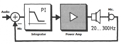
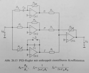
Now... Recently I remembered a schematic in the good old Tietze/Schenk electronics engineering study-book from decades ago and derived the idea to achieve optimal feedback dimensioning without a lot of math : A feedback system which adjusts the proportional (gain), integration and differentiation parts of the control loop adjustable individually. Well, the differentiation part is not needed here (omit the "R3" branch), but adjusting gain and integration individually, should enable finding an optimum feedback configuration relatively easily with a square wave input and measuring to acoustic signal ... right? The results would then be transferred into the simple one-OPAmp-circuit shown earlier in the thread.

Thinking a bit further f(I) is already known with 32Hz from the original design and may be OK to stay, so the adder gain and the microphone gain seem to be the real "tuning knobs" ...
So, it seems I'm on a possibly successful path. Or am I overkilling?
What's the advice, what's the thinking here folks?
Thanks and Regards,
Winfried
first of all my sincere apologies for leaving the subject. I was completely distracted by family related issues, i.e. am now a grandpa.
In the mean time major changes happened to the Omega project and the complete old speaker electronics are is being replaced with ChipAmps, new power supplies employing active rectification, a transformer starter circuit and transformer snubbing, remote on/off, LM317/337 supply, symmetrical/balanced inputs and ...
Which also brings me back to the acoustic feedback issue covered here.
So thanks for all your valuable posts! I'm going to thankfully take the advice posted by bolserst (and others) seriously as soon as I have the Chipamps working with the new power supply.
The main issue with the new Poweramp section is, that the Amp gain is not 35 dB as in the original B&M implementation, but only 26dB. This would mean that I need 10 dB more gain elsewhere in the loop, so would probably have to change the diff. Amplifier gain accordingly. right?
Now... Recently I remembered a schematic in the good old Tietze/Schenk electronics engineering study-book from decades ago and derived the idea to achieve optimal feedback dimensioning without a lot of math
: A feedback system which adjusts the proportional (gain), integration and differentiation parts of the control loop adjustable individually. Well, the differentiation part is not needed here (omit the "R3" branch), but adjusting gain and integration individually, should enable finding an optimum feedback configuration relatively easily with a square wave input and measuring to acoustic signal ... right? The results would then be transferred into the simple one-OPAmp-circuit shown earlier in the thread.Thinking a bit further f(I) is already known with 32Hz from the original design and may be OK to stay, so the adder gain and the microphone gain seem to be the real "tuning knobs" ...
So, it seems I'm on a possibly successful path. Or am I overkilling?
What's the advice, what's the thinking here folks?
Thanks and Regards,
Winfried
Attachments
You would need to measure the open loop response and tune that to some goal. It appears that the original open loop response is a band pass with first order slopes: a second order highpass (woofer in box, say at 60 Hz) combined with a first order low pass (electronics, say at 30 Hz). The woofer to microphone transfer function is likely to have resonances at high frequencies, so somewhere in the electronic part of the loop there must be a low pass filter.
For better control at some frequency range you need to increase the gain at the range at which the control is active. One way to accomplish that is by changing the first order low pass to a second order one and place it at or above the woofer resonance frequency. Now you have a band pass response with second order slopes. These have plus and minus 180 degree phase shifts. You cannot have 180 degree phase shift at the gain crossover frequencyies so you have to bend the phase a bit back towards 0 degrees using lag and lead compensators. 45 degrees shift (resulting in a net +-135 degrees) is sufficient.
An easier way is the PI controller you mentioned + a low pass. Let's analyse the open loop response. Start with the woofer to microphone transfer function, which is a second order high pass (~60 Hz) plus some resonances at high frequencies (~1 kHz). A second order high pass will have a 180 degree phase shift below the cut off frequency (~60 Hz). The 'P term' of the PI controller sets the open loop gain. The 'I term' works as a lead compensator to reduce the phase shift at the lower gain crossover frequency (~30 Hz). Then a low pass filter makes sure the open loop gain decreases below 0 dB before the resonances occur (~1 kHz).
Note that the open loop response includes high pass filters in the amplifiers. It's easiest if these are far away from the lower gain crossover frequency, otherwise they bend the phase even further away from 0 degrees at the lower gain crossover frequency.
Last edited:
A good way to see if MF is working is to examine the signal to the driver(s). You should see it is NOT flat and with some wiggles and there's a cut where the driver flaps (sealed or tuned box esp region below tuning) and a boost at low freq where a sealed box holds the drivers back. Also, and this will sound odd, the signal should show extra HD as a corrective to the driver. That's how you know MF is ALIVE.
Using REW to track electrical signals is more stable than loose acoustic measures - although no substitute for sound output. You can work with the simple basic comparison with is simply to a standard amp with no MF pre-amp driving the speaker, rather than worry about disabling the MF circuitry, just unplug it.
If working, it will be a very obvious A/B improvement percussive instruments.
Original circuit seems pretty good. I'd try to get performance measurements with that. You aren't moving forward until you start testing, then you can apply the comments of Bolserst and TBTL.
The electrets may be acting as accelerometers more than catching the breeze as mics, or just choice of name.
If being a grandpa is a valid excuse for procrastination, I can be a 14X procrastinator. Good excuse or not, congratulations.
B.
Hi folks,
sincere thanks for your elabotate comments and advice!
One Q of understanding:
I'm in the middle of building the new active electronics, like Power Amp and Supply boards featuring chip-amps, balanced inputs, active rectification and transformer snubbing. So, it will be a couple of weeks until I can show progress.
Thanks a bunch!
Winfried
sincere thanks for your elabotate comments and advice!
One Q of understanding:
What does the abbreviation "HD" mean?... the signal should show extra HD as a corrective to the driver ...
I'm in the middle of building the new active electronics, like Power Amp and Supply boards featuring chip-amps, balanced inputs, active rectification and transformer snubbing. So, it will be a couple of weeks until I can show progress.
Thanks a bunch!
Winfried
What does the abbreviation "HD" mean?
Harmonic distortion.
When you run a freq plot with REW, it does the freq plot and without further bidding, shows you the HD plot too.
REW - Room EQ Wizard Room Acoustics Software
REW - Room EQ Wizard Room Acoustics Software
B.
- Status
- This old topic is closed. If you want to reopen this topic, contact a moderator using the "Report Post" button.
- Home
- Loudspeakers
- Subwoofers
- Optimising Bass Microphone Servo control