Brian, just wondering where you were with this. Did you finalize a design?
I should be starting the build early in the new year. I was going to start it this week, but got distracted by other projects. Basically I'm going to build the first sim that I started this thread with.
I should be starting the build early in the new year. I was going to start it this week, but got distracted by other projects. Basically I'm going to build the first sim that I started this thread with.
Well, I can't wait to see pictures of the saw dust.
Are you going to flare the port exit or keep it straight, as designed?
Well, I can't wait to see pictures of the saw dust.
Are you going to flare the port exit or keep it straight, as designed?
Keeping it straight. Particle velocity at peak output is going to be so low that flaring it is likely to make no difference.
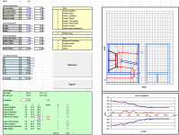
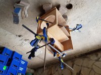
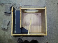
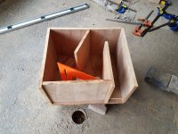
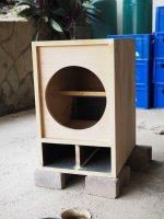
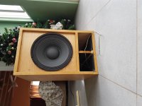
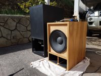
Some build pics. I opted for a 50 Hz MLTL variant.
I was hoping to have it finished by tomorrow afternoon (in time for a beach party), but the weather said otherwise . Probably not a good idea to bring an MDF enclosure out to the beach when there's a chance of rain anyway.
I was hoping to have it finished by tomorrow afternoon (in time for a beach party), but the weather said otherwise
. Probably not a good idea to bring an MDF enclosure out to the beach when there's a chance of rain anyway.Attachments
Sweet ! - it should kick better than a small port BR - it could make a nice Econowave type too
Probably not good for a full-range design. While the driver offset should kill must of the 200 Hz organ-pipe resonance, there's the other one at 300 Hz to deal with. It might be lower than sim'd (the folds may help to tame it), but let's see what the measurements say....

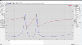
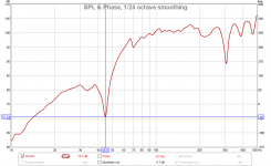
First measurement I did was the system's impedance curve. Usually this is the first measurement I always do, because it makes no sense to me to schlep out all the measuring equipment just to find out that the box has a leak somewhere, or the build does not match the sim or there's too much panel flex.
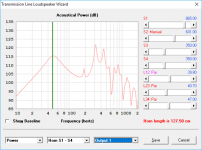
The measured curve shows that the lowest resonance point is about 0.4 Hz or so above what was predicted by the sim - not surprising as I've run out of polyester fiberfill and the enclosure has only half of the stuffing that was included in the sim! With the proper stuffing, the resonance point should be almost an exact match - another "win" for the Advanced Centerline Method.
The upper impedance peak frequency is almost an exact match for the Hornresp sim but of course its magnitude is a bit lower because Hornresp does not take box losses into consideration - 74 Ohms vs 87 Ohms in the sim. There should be a way to work out the box losses from the difference in the impedance peaks.
The lower impedance peak is slightly wider and higher in frequency than predicted by the sim, but this seems to be par for the course - basically every build I've done so far based on a Hornresp sim reflects this. I'm curious as to the reason why, but haven't come up with a suitable explanation for it.
Even the tiny ripple just above 300 Hz matches the Hornresp sim. What doesn't match though is that ripple around 145 Hz. Panel resonance maybe? It is a 3.5 cu.ft. (gross) box built out of 0.75" MDF, but I did add a small brace across the back of the top panel and side panels are braced by an internal panel that's part of the MLTL fold.
It's ******* down with rain outside at the moment (MDF survivability=zero), so I may do some close-miked measurements next.
The measured curve shows that the lowest resonance point is about 0.4 Hz or so above what was predicted by the sim - not surprising as I've run out of polyester fiberfill and the enclosure has only half of the stuffing that was included in the sim! With the proper stuffing, the resonance point should be almost an exact match - another "win" for the Advanced Centerline Method
. The upper impedance peak frequency is almost an exact match for the Hornresp sim but of course its magnitude is a bit lower because Hornresp does not take box losses into consideration - 74 Ohms vs 87 Ohms in the sim. There should be a way to work out the box losses from the difference in the impedance peaks.
The lower impedance peak is slightly wider and higher in frequency than predicted by the sim, but this seems to be par for the course - basically every build I've done so far based on a Hornresp sim reflects this. I'm curious as to the reason why, but haven't come up with a suitable explanation for it.
Even the tiny ripple just above 300 Hz matches the Hornresp sim. What doesn't match though is that ripple around 145 Hz. Panel resonance maybe? It is a 3.5 cu.ft. (gross) box built out of 0.75" MDF, but I did add a small brace across the back of the top panel and side panels are braced by an internal panel that's part of the MLTL fold.
It's ******* down with rain outside at the moment (MDF survivability=zero), so I may do some close-miked measurements next.
Attachments
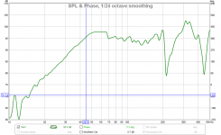
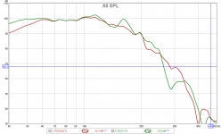
Some close-miked measurements. Interesting results.
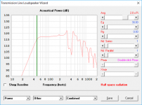
From the driver's response, it looks like the notch is a few Hz below what the impedance curve (and what Hornresp) suggests. I noticed this with the last build as well. Strange. If you go by the "notch", this design would be tuned too low, but the impedance curve suggests almost perfect alignment with the sim.
From the vent's response, it looks like the 200 Hz organ-pipe resonance is reduced, but better positioning of the driver can reduce it even further. I'm hoping that once the cabinet is properly stuffed, the effective offset point will be changed (as the sim suggests), improving the nulling of that organ-pipe resonance. In hindsight, I should have left the baffle removable for further experimentation with the position of the driver to "fine tune" the offset point.
I used REW to generate a combined response of the driver and the vent. Even with the offset not being perfect, the massive dip that would have appeared around 200 Hz (if the driver was mounted right at the start of the line, rather than offset) is almost completely eliminated. The response of this alignment is basically extended up to about 300 Hz, where once again a major dip in the response manifests itself.
Attachments
- its looking very good, tuning and response-wise. Do you have another PA310 in the POC-Th? or is this a shared driver? - just wondering how they will subjectively compare.
me too
- its looking very good, tuning and response-wise. Do you have another PA310 in the POC-Th? or is this a shared driver? - just wondering how they will subjectively compare.
I'm now using an Eminence Kappalite 3012LF in the POC3 TH. specs-wise, you can swap the 3012LF for the PA310 with only minor changes in frequency response. The 3012LF does have a higher rated Xmax however.
While tempted to do a subjective comparison, note that the POC6 MLTL isn't really finished yet. The damping is an important aspect of the design, and ran out of damping material. Hopefully I can get that sorted out tomorrow.
Run without an x-over, it's not impressive. Then again, neither was POC3
. Those out of band resonances really need to be addressed. I'll hook it up to the car amp (1.2kW, 24dB/octave x-over) tomorrow to see if that makes any difference. 1.2kW is way over what these two systems can safely manage (ask me how I know this, LOL), but I don't plan on turning it up that loud for the testing.- its looking very good, tuning and response-wise. Do you have another PA310 in the POC-Th? or is this a shared driver? - just wondering how they will subjectively compare.
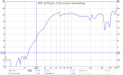
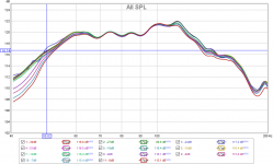
POC3-TH vs. POC6-MLTL. Who "wins"?
Attachments
POC3-TH vs. POC6-MLTL. Who "wins"?
Well, here's what the frequency response of both looks like, when measured under the same conditions. It's not perfect, as the response would be affected by nearby items (like my car!) and the LP filters engaged on the car's amp and head unit, but it can serve to make a useful comparison between the two systems.
Note that the POC3-TH was designed for the Dayton PA310 driver, but it's now loaded with an Eminence 3012LF. The former is an 8 ohm driver and the latter is a 4 ohm driver, but the specs suggest that they are swappable with only minor changes in the FR at bass frequencies.
Of course the TH walked all over the MLTL from 50 Hz and below. The difference was noticeable and measurable. About 4dB more @50 Hz and 6dB more @40 Hz. I was expecting this because the MLTL is a smaller box (2.4 cu.ft. vs. about 4 cu.ft. net) tuned to a higher frequency. Between 70 Hz and 100 Hz though the response was basically identical, and above 100 Hz the MLTL measured better. There may be a bit of "confirmation bias" here, but I thought the MLTL sounded audibly a bit better too than the TH when playing back a few music tracks - except that it had noticeably less output at lower frequencies. This was for example very noticeable when playing the Kolsch remix of London Grammar's "Hell To The Liars", which has lots of 40 Hz content.
The MLTL is of course smaller, and that smoother response between 100 Hz and 200 Hz should really help with integration into a complete system.
Maybe I should have opted for the 40 Hz MLTL...
Attachments
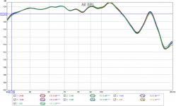
Some linearity testing suggests compression of up to 2dB at 48 Hz and 1.5dB at 50 Hz. I stopped the testing at this point, even though I wasn't seeing THD reaching 10% in the passband because distortion was VERY audible just below Fb. The big vent does make a difference. However, THs are much better in this regard too - the POC3 TH shows compression of 0.3dB or less once the driver in driven within its linear region. Hey, it's a 350 cm^2 vent versus a 925 cm^2 one, so....
Attachments
- Status
- This old topic is closed. If you want to reopen this topic, contact a moderator using the "Report Post" button.
- Home
- Loudspeakers
- Subwoofers
- Simple bass unit using the Dayton PA310