I see L34 as a "rubbery/flexible" section. The sim does not change much with a shorter or longer L34. I use the distance from the end of the tapped pipe section to the center of the cone/voicecoil as a guesstimate length. It is not an issue in real life. You don't create a great design by creating a perfect match between a theoretical and greatly simplified mathematical simulation and a measured response.
I judge my designs based on real life performance.
Cheers,
Johannes
L34 does have to be set to 0.01.
YOUR S3-S4 volume needs to be added to S2-S3 or S4-S5.
I cheated and added YOUR L34 to L23 in pic 1 and to L45 in pic 2.
I doubled Re from 5.05 to 10.10 in both 2nd graphs.
Attachments


Great to see someone brave enough to make some sawdust instead of endless theoretical bickering!
I hope it sounds as good as my ROAR12. I am very happy and pleased with my ROAR12. I have compared it to several different experimental tapped horns and tapped pipes (non-expanding) of my own design, and to both THAM12 and THAM15 with success.
Cheers,
Johannes
I hope it sounds as good as my ROAR12. I am very happy and pleased with my ROAR12. I have compared it to several different experimental tapped horns and tapped pipes (non-expanding) of my own design, and to both THAM12 and THAM15 with success.
Cheers,
Johannes
Let's go from theory to practice.
Nice!
If you still have the possibility I would suggest making the holes in the two braces bigger in diameter and perhaps increase the number of holes to increase the air flow, this is only a suggestion and I'm not sure it is necessary, you decide, and I'm very grateful that you share your work, looks good, thank you!
L34 does have to be set to 0.01
The transition from the tapped pipe to the front-resonator is a quite complex area. If you measure the distance on the plans or in a real ROAR you will see that there is a real physical distance from the end of the tapped pipe to the center of the driver. Due to the quite intense pressure from the front-resonator the exit of the tapped pipe section "sees" a more narrow angle then the physical 90 degree corners where it exits into the front-resonator.
I have found it equally wrong to use 0.1 cm as 25 cm as L34 in the ROAR12.
Real world measurements tend to show something in the middle of the two. Since Hornresp uses very simplified mathematical models I don't see the need to obsess over the exact correlation between the sims and the real world results.
Hornresp is a great tool and I am very grateful for the opportunity to be able to use it. I have expressed my gratitude to David McBean several times, but one must always remember that it is a simplified tool. If you want to make a perfect simulation, you must simulate every atom and every energy-level in the horn and its surroundings. It would be a quite daunting task.
After all these years of designing and building loudspeakers and tapped horns I prefer to focus on all these details "between the lines", which matters at least as much as the simulated response. The simulated response is a first crude draft, verifying the over all behavior of the design. The shape of the mouth makes a huge difference (see the numerous threads about the keystone design or the Carlson designs). A real tapped horn is a much more complex beast to design then a simple Hornresp simulation, even if the Hornresp simulation is a great start and a great indicator of the expected performance.
Once you have a simulation you like and know (based on many years of design-work and field-use) that translates into a great sounding and performing tapped horn, you have only done 10% of the work needed.
The THAM-series took several years from the first drafts to the plans published on Anders Martinssons blog.
I don't want to write much more about it here when there are trolls who contribute great things like "This whole thread is ridiculous" in response to our efforts. It is not constructive in any way. I would call it rude and quite hostile.
Cheers,
Johannes
I did a lot of tests with FLH and TH prototypes using large holes in braces or no holes at all.
Holes are only needed if braces are blocking the soundwave direction or are so huge that it does damage to the required internal volume.
In this case I see no problem because the soundwaves are being directed horizontally anyway. Braces placed in 'flow' with the soundwave direction.
Speaking of which, I have read some discussion about placing braces can prevent cancellation of soundwaves that bounce up and down in the folded horn enclosure path.
If you still have the possibility I would suggest making the holes in the two braces bigger in diameter and perhaps increase the number of holes to increase the air flow
Hi, Mr. Martinsson!
There are a 20-50-70 mm free space between the brackets and the driver cone, so i choosed to pick up most of the available stiffness. Little V-shaped cutouts in the brackets are needed in the case of long-throw drivers.
If you saw i also choosed to use slightly modified bracketing matrix, the driver panel are clamped by four perpendicular brackets.
The transition from the tapped pipe to the front-resonator is a quite complex area. If you measure the distance on the plans or in a real ROAR you will see that there is a real physical distance from the end of the tapped pipe to the center of the driver. Due to the quite intense pressure from the front-resonator the exit of the tapped pipe section "sees" a more narrow angle then the physical 90 degree corners where it exits into the front-resonator.
I have found it equally wrong to use 0.1 cm as 25 cm as L34 in the ROAR12.
Real world measurements tend to show something in the middle of the two.
There might be some merit to this, since if you laid it out via the centerline or advanced centerline method it would not be a 90 degree expansion. But you didn't do that, did you? As your own words suggest, you just guessed.
I don't want to write much more about it here when there are trolls who contribute great things like "This whole thread is ridiculous" in response to our efforts.
I could say the same when you continue to make comments like ...
Since Hornresp uses very simplified mathematical models ...
... one must always remember that it is a simplified tool.
The simulated response is a first crude draft,
A real tapped horn is a much more complex beast to design then a simple Hornresp simulation ...
And on and on ....
I find this attack on Hornresp exceptionally offensive. Many of the best designers don't need to do countless iterations to make the sim match the measurement because they do accurate sims in the first place. These designers certainly would not agree that a good sim is only the first 10 percent of the work. You absolutely do not need to account for every atom in the horn to make the sim match the measurement. When you clearly have made no attempt to sim the enclosure properly in the first place you have no grounds to attack the simulator.
All I can really do is go back again to the BC sub fiasco. You claimed the BC sub was a tapped horn, you claimed it had this W shaped frequency response and you claimed it could not be simulated properly because the air velocity created a vortex equating to a virtual final segment at the end of the horn made of pure air. I showed clearly that all of this was complete bunk and IIRC you never admitted that you were wrong about any of it. Add in the current level of attacks on Hornresp and there's no way I'm going to remain silent as you continue to make grievous errors in all aspects of the design process.
You absolutely do not need to account for every atom in the horn to make the sim match the measurement.
Yeah!
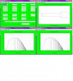
But why different sims shows different results?
For example, this 6-order series box can be calculated in BassBox with that results:


Green colour - ROAR18, red colour - suggested BassBox optimum.
Hi all,
I remodelled the "Roar18" and used the volume per segment method, advanced centre-line and cone-volume to increase accuracy. Used also a slightly different method for the symmetric split-path, that gave me better results in previous projects.
Regards,
Djim
I remodelled the "Roar18" and used the volume per segment method, advanced centre-line and cone-volume to increase accuracy. Used also a slightly different method for the symmetric split-path, that gave me better results in previous projects.
Regards,
Djim
Attachments
Last edited:
Hi all,
I remodelled the "Roar18" and used the volume per segment method, advanced centre-line and cone-volume to increase accuracy. Used also a slightly different method for the symmetric split-path, that gave me better results in previous projects.
Regards,
Djim
Hello gentlemens.
Thank you for sharing your project and experience. Seems the ROAR usable range is 40-125hz. For home use will the AE TD18H work? The target is high efficiency, dynamic 35-150hz.
TD18H+8ohm
Fs: 29Hz
Qms: 5.9
Vas: 390 L
Cms: .19 mm/N
Mms: 165 g
Rms: 5.03 kg/S
Xmax: 14 mm(peak)
Xmech: 25 mm(peak)
Sd: 1218 sqcm
Vd: 3.42L (p-p)
Qes: .23
Re: 5.6 ohm
Le: .41 mH
Z: 8 ohm
Bl: 27.06 T/m
Pe: 1000W (cont.)
Qts: .22
1WSPL: 98.15 dB
2.83V: 99.7 dB
Thank you.
Last edited:
Thank you for taking the time and efforts to dive deeper into the design, it's greatly appreciated.I remodelled the "Roar18" and used the volume per segment method, advanced centre-line and cone-volume to increase accuracy. Used also a slightly different method for the symmetric split-path, that gave me better results in previous projects.
A couple of questions.
Regarding the front resonator length, this is a tricky area, how do we best describe the resonator function? to my mind (not saying that I'm right) is to look at the length of the volume establishing the resonance, that would be distance between the driver baffle and the aperture, 83,4cm.
If one shortens the front resonator length in the simulation the sensitivity would shift to the upper end of the passband, as per you simulation.
Personally I'm not sure which of these interpretations is correct, maybe the truth is somewhere in between the two.
Another interesting take in you interpretation is the S1-S2 distance (L12) that goes from the center of the driver to the edge, this is also a bit of a tricky area, and again I'm not sure which way is the correct one, but it is good to see other was of looking at the system.
I will have a closer look at the work you have done within short, very interesting, thank you, br / Anders
Yes I noticed that, nice touch! looks good, and I'm sure it makes the enclosure very rigid and stable.If you saw i also choosed to use slightly modified bracketing matrix, the driver panel are clamped by four perpendicular brackets.
Thank you for keeping us posted on your progress, I'm personally very keen to hear what you think of both the build and the result, best regards / Anders
Thank you for keeping us posted on your progress, I'm personally very keen to hear what you think of both the build and the result, best regards / Anders
It's time to roar up a bit!


The first impression was spoiled by apples falling to the ground from around apple trees.
")
DCX Driverack PA+ was used for all signal conditioning purposes and amplification was provided by very mighty amps.

For home use will the AE TD18H work?
Yes, it will work.
Black line - your AE TD18H, gray - my RCF LF18X401.

But are you really want to feel an earthquake in your house?
The first impression was spoiled by apples falling to the ground
Thanks for pictures and first impressions BesPav!!!
Nice to see someone test our ROAR-series.
For home use will the AE TD18H work?
Listening to my single ROAR12 I would not want to use a ROAR18 indoors in a normal residential home.
Thanks for your speedy simulation of the AE TD18H driver BesPav!
It seems to be a nice suitable driver for a ROAR18, even though I concur in your "earthquake" comment.
Cheers,
Johannes
This is the second time our designs has caused unintended damage, Magic Johnson in Finland reported that he levitated the gravel on the ground around a couple of THAM15's and some paint chips falling of the nearby house, and now this, perhaps we should post warningsThe first impression was spoiled by apples falling to the ground from around apple trees.
Could not help but laughing out loud at this comment, brilliant, thank you BesPav
I hope you found the build worth while and that you are satisfied with the results.
Hi all,
I remodelled the "Roar18" and used the volume per segment method, advanced centre-line and cone-volume to increase accuracy. Used also a slightly different method for the symmetric split-path, that gave me better results in previous projects.
Regards,
Djim
Looking at the layout of the ROAR, I don't think that S1-S2 length is correct in your sim - should be more like 0.1cm as per the alternate suggestion, as the center of the driver is right over the start of the path. The cone volume can be modeled using Atc and Vtc (set Atc to be the driver's Sd). The baffle cutout for the driver can also be modelled by setting Ap1 and Lp (Lp=baffle thickness and Ap1=Sd of the cutout).
I also think that the "advanced centerline" method loses some accuracy when you have rapid expansions around a corner as is the case here with that last corner before the driver, but it's better than nothing here. To be honest, if I was doing this design, I wouldn't use so many non-expanding sections - looking at it, it should only take a few minor tweaks to convert it to a single-expansion TH with a smooth expansion from S1 to S4, by mounting the internal panels at a slight angle to the path and adjusting their lengths accordingly. And then I'd be pretty sure that what I sim is what I get. In fact, looking even closer at it, it should be possible to convert it to a dual expansion TH with the driver at S3 instead of S4, but a bit more path length would be lost in the process.
Thanks for pictures and first impressions BesPav!!!
Nice to see someone test our ROAR-series.
No-no, vice versa, thank you, Johannes, for sharing design idea and providing all needed dimensions and layout. Based on yours choosed dimensions cutting sheets was very simple and provides very small waste.
Could not help but laughing out loud at this comment, brilliant, thank you BesPav
Yea, you are welcome for such kind of comments!
I hope you found the build worth while and that you are satisfied with the results.
Yes, the build was simple, all panels are rectangular and have no sides with angle cuts.
The one issue is the mounting sequence.
I suppose it would be better to let following builders to know good practice in assembling - start from connecting driver panel and middle pipe panels. May be you can show this in your 3D CAD.
Second impression was taken after DBX AutoEQ with RTA Mic. Fast, deep, uncoloured bass, true without long wooooofff like some bandpasses do.
I've checked DBX parametric EQ settings in Hornresp and found this:

Without EQ'ing bass was track-dependant, some tracks bass fell into dips, some tracks hits the peak.
Saying in different words, some tracks has pressed guts out and the eggs shrank from fear, some tracks sounded unconvinced and poorly.
The one of the best i've found is this:
Master of Tides - Lindsey Stirling - YouTube
I've checked DBX parametric EQ settings in Hornresp and found this:
View attachment 631026
What were the DBX parametric EQ settings used to flatten the response?
The response at the upper end of the passband drops like a rock. I've tried using EQ settings that resulted in a response like that between 100 Hz and 200 Hz for my subwoofers. I didn't like the results at all.
- Home
- Loudspeakers
- Subwoofers
- ROAR18