Hi Everyone.
First I would like to thank everyone that contributes to diyAudio, and makes all this possible. I learn new things all the time.
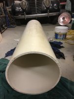
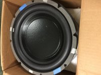
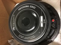
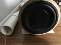
A while back I purchased 2 LAB12s, because they seemed to be versatile and well made. They could be used in closed box, bass reflex, T-line, horns and more. I didn't really have a direction for this project, until I picked up this piece of PVC pipe that was being thrown away. Can't beat free!
The PVC pipe is 13 inch diameter x 5 feet. First I simulated a closed box then a bass reflex using Hornresp. The closed box with a driver mounted on each end looked pretty good. I think the Qtc=.69. I'm not sure how to add pictures in the middle of my post, so I will attach them at the bottom. I will post the BR images later.
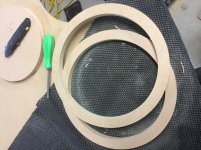
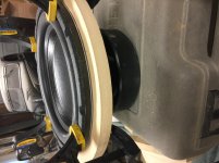
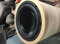
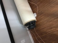
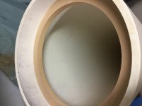
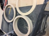
I figured I would build it sealed first and listen to it for awhile before going ported. So I started cutting rings out of some MDF that I had on hand. I used a router and a Jasper jig to cut them out. I cut two rings for each side that fits inside the pipe, one ring that overlaps the end, and one ring to give the driver a flush mounted look. I used 10-24 hex head screws and T-nuts. Glued the T-nuts using gorilla glue, then chased the threads with a tap. Glued the rings together using wood glue. Then glued the rings to each end using gorilla glue.
I will split the post up so maybe it will make more sense with the pictures.
regards,
Matt
First I would like to thank everyone that contributes to diyAudio, and makes all this possible. I learn new things all the time.
A while back I purchased 2 LAB12s, because they seemed to be versatile and well made. They could be used in closed box, bass reflex, T-line, horns and more. I didn't really have a direction for this project, until I picked up this piece of PVC pipe that was being thrown away. Can't beat free!
The PVC pipe is 13 inch diameter x 5 feet. First I simulated a closed box then a bass reflex using Hornresp. The closed box with a driver mounted on each end looked pretty good. I think the Qtc=.69. I'm not sure how to add pictures in the middle of my post, so I will attach them at the bottom. I will post the BR images later.
I figured I would build it sealed first and listen to it for awhile before going ported. So I started cutting rings out of some MDF that I had on hand. I used a router and a Jasper jig to cut them out. I cut two rings for each side that fits inside the pipe, one ring that overlaps the end, and one ring to give the driver a flush mounted look. I used 10-24 hex head screws and T-nuts. Glued the T-nuts using gorilla glue, then chased the threads with a tap. Glued the rings together using wood glue. Then glued the rings to each end using gorilla glue.
I will split the post up so maybe it will make more sense with the pictures.
regards,
Matt
Attachments
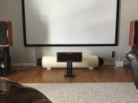
So I asked my wife for some help getting this thing in the house, and she did, so I think she is okay with it.") I put it at the front of the room, where I intend it to go when I'm finished. I was able to do impedance and frequency sweeps using DATS and REW. And here are some more pictures.
I put it at the front of the room, where I intend it to go when I'm finished. I was able to do impedance and frequency sweeps using DATS and REW. And here are some more pictures.
Regards,
Matt
I put it at the front of the room, where I intend it to go when I'm finished. I was able to do impedance and frequency sweeps using DATS and REW. And here are some more pictures.Regards,
Matt
Attachments
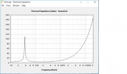
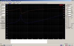
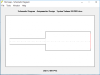
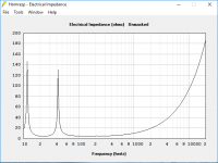
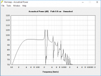
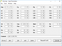
Here are the Hornresp, DATS, and REW images. Hornresp is pretty amazing it even shows the increase in impedance at about 225hz same as what the DATS measured.
I only simed one driver so the enclosure volume is halved. Hornresp is new to me, so if anyone has any comments or questions please don't hesitate to let me know.
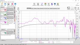
The REW image is with the mic at my seated position and the sub at the front of the room. No other subs are on and no EQ.
Regards,
Matt
I only simed one driver so the enclosure volume is halved. Hornresp is new to me, so if anyone has any comments or questions please don't hesitate to let me know.
The REW image is with the mic at my seated position and the sub at the front of the room. No other subs are on and no EQ.
Regards,
Matt
Attachments
-
 Hornresp image sealed impedance.png25 KB · Views: 139
 -
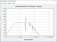 Hornresp image sealed Acoustical Power.png23.5 KB · Views: 144
 -
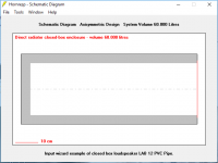 Hornresp image sealed Schematic.png12.7 KB · Views: 105
 -
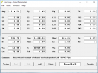 Hornresp image sealed Input screen.png18.3 KB · Views: 115
 -
 LAB12 PVC Pipe Sealed.jpg257.7 KB · Views: 102
 -
 REW In room LAB12 Sealed.png138.4 KB · Views: 142
Really cool sub build,
Even cooler wife--a keeper for sure. Plan on wrapping something around the tube, the greatness of tubes is they are so easy to finish!
Nice job and am looking forward to your readings.
Thanks. And yes she is a keeper. I plan on painting it. I have access to a spray both at a auto body shop. As far as color, I'm leaning toward white pearl, but that changes daily.
Regards,
Matt
I have been listening to the LAB12s sealed for about a week and I like the way they sound, but I think its time to try them in a bass reflex. I am running 2 other bass reflex subwoofers and a large sealed rear chamber bandpass subwoofer in the room currently.
In the sim I used only one driver and one 4" port. In reality two drivers and two 4" ports will be used. I should mention that when I'm done the drivers will be mounted with the cones out.
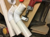
I picked up the 4" PVC pipe and 90s for the ports, so I guess it's time for the sub to go back out to the garage. I hope my helper is ready for more lifting.
Regards,
Matt
In the sim I used only one driver and one 4" port. In reality two drivers and two 4" ports will be used. I should mention that when I'm done the drivers will be mounted with the cones out.
I picked up the 4" PVC pipe and 90s for the ports, so I guess it's time for the sub to go back out to the garage. I hope my helper is ready for more lifting.
Regards,
Matt
Attachments
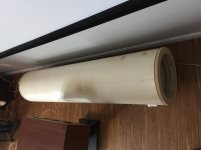
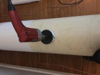
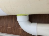
A little more progress has been made with this project, so thought I would post more pictures. This week I cut the holes for the ports, added some stuffing in the middle of the pipe, and cut the ports to length.
It was too cold in the garage, so I decided to cut the holes in place. The outside diameter of the 4" pvc is 4.5", so I picked up a 4.5" hole saw to cut the holes. Cutting the holes was much harder than I anticipated, what a pain. I used a 12" mitre saw to cut the pvc to length. I started with a longer port length, then cut 1" off at a time, then checking each time with an impedance sweep. I used some modeling clay to temporarily seal the port to the pipe for testing. There is a little more fine tuning needed before I start on the finish. So far I am happy with results.
Regards,
Matt
Attachments
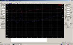
Here are some of the impedance sweeps.
The first image is a sweep with the port length of 25" and no stuffing.
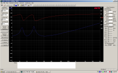
The second image has the same port length, but with about 1.5 pounds of poly fill in the middle of the pipe away from the ports. Notice the tuning and the impedance peaks are lower.
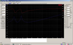
The third image is after cutting 3" off of each port and 1.5 pounds of poly fill. There is still a little more tuning to do. I may cut 1 more inch off of each port to raise the tuning a little.
Regards,
Matt
The first image is a sweep with the port length of 25" and no stuffing.
The second image has the same port length, but with about 1.5 pounds of poly fill in the middle of the pipe away from the ports. Notice the tuning and the impedance peaks are lower.
The third image is after cutting 3" off of each port and 1.5 pounds of poly fill. There is still a little more tuning to do. I may cut 1 more inch off of each port to raise the tuning a little.
Regards,
Matt
Attachments
Now that it's ported you have created a Mass Loaded Transmission Line. Closer to a 1/8wave instead of 1/4 as what is normally designed for, it's in that quasi TL/BR land. End loaded straight line
If the tube were subdivided in half length wise and the non ported end cut shorter by approx 1/3 internal line length would result in a 1/4wave MLTL tuned to about ~30Hz (off the top of my head).
The internal divider would fall short of where the current woofer is placed to allow the line to appear as a continuous length and driving it at the proper point. The objective is to maintain the cross sectional area through that bend behind the driver. To the line it appears as a simple fold. Doing this allows you to also brace the back of the lab12 motor by the divider.
Example, I have built an MLTL using a 6.5" midwoofer and 8" ID sonotube that is 45" long. Internally it's 74"and built as described above. The driver on this one is mounted in reverse, magnet out atm so mine are 48" end to end. The reason for the inversion was to not impede flow and to minimize turbulence internally. Like yours my driver also has the inverted dustcap. Just another thing that doesn't get in the way
You can model this with http://www.diyaudio.com/forums/software-tools/220421-transmission-line-modelling-software.html
A little more progress has been made with this project, so thought I would post more pictures. This week I cut the holes for the ports, added some stuffing in the middle of the pipe, and cut the ports to length.
It was too cold in the garage, so I decided to cut the holes in place. The outside diameter of the 4" pvc is 4.5", so I picked up a 4.5" hole saw to cut the holes. Cutting the holes was much harder than I anticipated, what a pain. I used a 12" mitre saw to cut the pvc to length. I started with a longer port length, then cut 1" off at a time, then checking each time with an impedance sweep. I used some modeling clay to temporarily seal the port to the pipe for testing. There is a little more fine tuning needed before I start on the finish. So far I am happy with results.
Regards,
Matt
You should have push-pull coupled the drivers for cleaner bass. See Steve's Compounded, Super-Duper Shiva/Sonotube(R) T-line Subwoofers for inspiration
Thanks for your input and suggestions, Greebster and zobsky.
I did try it in a push-pull configuration for about a day or so. My only concern with running it that way is I have kids and cats and dogs. The exposed driver and wiring is kind of a problem. For now I will run them dual opposed. The force canceling seems to work very well.
Interesting that you should mention t-line. I really like the way they sound with certain types of music. After glueing the baffles on each end I mounted one of the drives, I just couldn't wait to bring it in the house. So I wired up one of my Altec Lansing pro amps to the driver and let her rip. Everything in the garage was shaking and rattling. I couldn't believe how loud it would get with so little power. I modeled it in hornresp and did an impedance sweep. The sweep matched the model almost perfectly. If anyone is interested I could post the hornresp and dats images. Anyways, it's time.
Regards,
Matt
You could semi-enclose the push pull drivers in a PPSL manifold box and mate the box to the transmission line. Make the manifold as small as reasonably possible while still being able to install the driversThanks for your input and suggestions, Greebster and zobsky.
I did try it in a push-pull configuration for about a day or so. My only concern with running it that way is I have kids and cats and dogs. The exposed driver and wiring is kind of a problem. For now I will run them dual opposed. The force canceling seems to work very well.
Interesting that you should mention t-line. I really like the way they sound with certain types of music. After glueing the baffles on each end I mounted one of the drives, I just couldn't wait to bring it in the house. So I wired up one of my Altec Lansing pro amps to the driver and let her rip. Everything in the garage was shaking and rattling. I couldn't believe how loud it would get with so little power. I modeled it in hornresp and did an impedance sweep. The sweep matched the model almost perfectly. If anyone is interested I could post the hornresp and dats images. Anyways, it's time.
Regards,
Matt
Example of a PPSL manifold box .you would mate it to the TO as opposed to porting it like the picture shows. No more exposed drivers
http://waveboxes.com/Wave G/100_1147.jpg- Status
- This old topic is closed. If you want to reopen this topic, contact a moderator using the "Report Post" button.
- Home
- Loudspeakers
- Subwoofers
- Two LAB12s and PVC pipe build.