Long time since my last post here.. But I don't have any questions for most of my designs ")
This one is a little different.
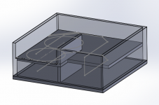
Right now I am designing a tapped horn for 2 18's. To keep it somewhat small, and tuned low, I am planning to keep S1-S4 small, and some folds to get the required length.
What is the minimal surface area for S1-S4 to make it work right? Is 1/2 x Sd ok?
Also, it will not be tapped, but surface area is constant. But I guess that doesn't really matter. HornResp simulations show that it will work with a constant surface area.
I added a image of the design I was thinking of in the attachment
This one is a little different.
Right now I am designing a tapped horn for 2 18's. To keep it somewhat small, and tuned low, I am planning to keep S1-S4 small, and some folds to get the required length.
What is the minimal surface area for S1-S4 to make it work right? Is 1/2 x Sd ok?
Also, it will not be tapped, but surface area is constant. But I guess that doesn't really matter. HornResp simulations show that it will work with a constant surface area.
I added a image of the design I was thinking of in the attachment
Attachments
Long time since my last post here.. But I don't have any questions for most of my designs
This one is a little different.
It looks a lot like my POC #3 design - see The Subwoofer DIY Page v1.1 - Projects : A "Proof of Concept" tapped pipe** - introduction
I suspect that once you work out the actual dimensions required to house two 18s, it will end up being impractical. The SS15 type fold is probably the best for an 18" TH for a number of different reasons, including keeping the mouth as square as possible.
I'm designing this one for a car for someone else. It is a SUV with the backseat removed, so the room is pretty big (48 x 48 x 20 inches).
I designed this one at exactly that dimensions. The only thing I am worried about is that there a 2 18's in there, and the surface area of S1-S4 is about the same as 1 18 inch woofer
I designed this one at exactly that dimensions. The only thing I am worried about is that there a 2 18's in there, and the surface area of S1-S4 is about the same as 1 18 inch woofer
Add two drivers in hornresp and see what happens
I already did. The frequency response looks good with 0.5x total Sd.
But lets say I am doing a BR box, for 2 18's. And the frequency response might look good with 1 4 inch port. Everyone knows that that is too small.
Does the tapped horn also have these kind of design rules?
Hi Michelp89,
It would be helpful if you would post the Hornresp Export file for your simulation.
The basic rule of thumb to start w/ a three segment tapped horn simulation would be S2=Sd/2, the mouth S4=2*Sd and L14=1/4 wavelength of Fb; beyond that you should let Hornresp be your guide.
If your design looks good in Hornresp, and does not look completely irrational (as the 4"Dia. duct for 2ea. 18" woofers), I would just go with it. The good thing about a smaller mouth is that it often provides more low end extension.
Also, it looks like that in your design you could reduce S2, and increase S4, or use the 4 segment simulation to provide more than one taper (the mouth then becomes S5). A smooth taper is not necessary for a subwoofer tapped horn, so you can build it as a stepped horn.
As Brian Steele said in Post #2 you need to "work out the actual dimensions"; then you need to re-simulate from the box data, etc...
Regards,
The BR thing was just an example
Hi Michelp89,
It would be helpful if you would post the Hornresp Export file for your simulation.
The basic rule of thumb to start w/ a three segment tapped horn simulation would be S2=Sd/2, the mouth S4=2*Sd and L14=1/4 wavelength of Fb; beyond that you should let Hornresp be your guide.
If your design looks good in Hornresp, and does not look completely irrational (as the 4"Dia. duct for 2ea. 18" woofers), I would just go with it. The good thing about a smaller mouth is that it often provides more low end extension.
Also, it looks like that in your design you could reduce S2, and increase S4, or use the 4 segment simulation to provide more than one taper (the mouth then becomes S5). A smooth taper is not necessary for a subwoofer tapped horn, so you can build it as a stepped horn.
As Brian Steele said in Post #2 you need to "work out the actual dimensions"; then you need to re-simulate from the box data, etc...
Regards,
I will post HornResp exports later today
But lets say I am doing a BR box, for 2 18's. And the frequency response might look good with 1 4 inch port. Everyone knows that that is too small.
Does the tapped horn also have these kind of design rules?
The issue in this example is port velocity. You can easily check velocity at your horn mouth with Hornresp.
Yes, tapped horns have the same "design rules", you don't want a huge velocity at the mouth, but since tapped horn mouths are usually significantly larger than a 4 inch port the mouth size is not usually a problem. It doesn't hurt to check velocity at your horn mouth, it only takes a second.
I would think that the dominant issue to look at in this design is the fact that the two drivers tap into the line at very different points. This will cause a very uneven load on each individual driver, one will be stressed much more than the other and they wiil likely have very different excursion. You can check this in Akabak. Josh Ricci has written about this issue several times, most recently in his new Zod Audio MAUL design, he has a detailed writeup on how this issue affected his design posted at the data-bass forum.
I wouldn't build this design as shown. I would go for a symmetrical layout that allows both drivers to tap into the line at the same point. That would also allow for an easier build, but with the compromise being that the aspect ratios are much higher.
I wouldn't build this design as shown. I would go for a symmetrical layout that allows both drivers to tap into the line at the same point. That would also allow for an easier build, but with the compromise being that the aspect ratios are much higher.
Good point about the drivers in different points in the line. I never took the time to learn Akabak, but I will soon
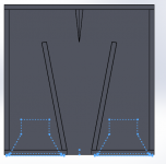
And I think, with these dimensions, it will be hard to build a tapped horn, mostly because of the required length. I think I am going for a T-line, added a image of the idea in the attachment
And I think, with these dimensions, it will be hard to build a tapped horn, mostly because of the required length. I think I am going for a T-line, added a image of the idea in the attachment
Attachments
- Status
- This old topic is closed. If you want to reopen this topic, contact a moderator using the "Report Post" button.
- Home
- Loudspeakers
- Subwoofers
- Tapped horn surface area