Building this well known horn of Cowan's has been pretty exciting for me, being able to experience DIY bass this loud (even though it's really not much compared to some of you guys) for the first time, especially from a Tapped Horn. Here is some of the progress I've done and some thoughts that have been going through my mind during this.
I'm powering this with an XLS 1,500 and used 3 quarter inch birch ply and used bracing along most of the length of the front and back baffle. When I built this I didn't know of any miss-measurements by Cowan, so I guess this isn't perfect. The driver is wired through the baffle before reaching the terminals on the back. The whole thing was constructed with MANY wood screws and PL400. I used two layers of Duratex to coat the whole thing.
No measurements have been made since constructing, just breaking-in and lots of listening. The driver is the Dayton RSS315HF-4 12"—something I got as a first try budget driver for this design knowing it'll probably have bad resonances and dips. I'd like to get a DSP to flatten the response soon, but I'll probably switch out the driver altogether for a better suited one even later.
My main concern is the gap between between the back wall and the baffle. Cowan said to make this 48mm, but upon rereading my notes on the design, my conversion to inches was .1" off, making it 1-7/16" instead of 1-14/16," or 46mm. I have the driver mounted on the opposite side of the baffle with the surround sticking through, so it's 3/4" already further away from the back. Is this too close? Is this going to effect output in anyway? Maybe I'm nitpicking, but this seems close for any driver to be from a wall, especially with its xmax. Let me know if I'm over concerned.
My other concern was the statements surrounding his original measurements. There are a few different measurements on his TH page, so I won't be talking about the ones he obviously states as incorrect. I was initially attracted to it because of the low end response at such high SPL, but after hearing his measurements were incorrect, I'm not sure which graphs/claims to believe. Is his 30hz horn not as low, or not as loud—or both—as he claimed and showed?
This one isn't as a major concern, it's just a comfort to know his actual results.
Thanks.
Didn't take many pictures but I have these:
Curing after applying the duratex

Looking into the mouth.

I'm powering this with an XLS 1,500 and used 3 quarter inch birch ply and used bracing along most of the length of the front and back baffle. When I built this I didn't know of any miss-measurements by Cowan, so I guess this isn't perfect. The driver is wired through the baffle before reaching the terminals on the back. The whole thing was constructed with MANY wood screws and PL400. I used two layers of Duratex to coat the whole thing.
No measurements have been made since constructing, just breaking-in and lots of listening. The driver is the Dayton RSS315HF-4 12"—something I got as a first try budget driver for this design knowing it'll probably have bad resonances and dips. I'd like to get a DSP to flatten the response soon, but I'll probably switch out the driver altogether for a better suited one even later.
My main concern is the gap between between the back wall and the baffle. Cowan said to make this 48mm, but upon rereading my notes on the design, my conversion to inches was .1" off, making it 1-7/16" instead of 1-14/16," or 46mm. I have the driver mounted on the opposite side of the baffle with the surround sticking through, so it's 3/4" already further away from the back. Is this too close? Is this going to effect output in anyway? Maybe I'm nitpicking, but this seems close for any driver to be from a wall, especially with its xmax. Let me know if I'm over concerned.
My other concern was the statements surrounding his original measurements. There are a few different measurements on his TH page, so I won't be talking about the ones he obviously states as incorrect. I was initially attracted to it because of the low end response at such high SPL, but after hearing his measurements were incorrect, I'm not sure which graphs/claims to believe. Is his 30hz horn not as low, or not as loud—or both—as he claimed and showed?
This one isn't as a major concern, it's just a comfort to know his actual results.
Thanks.
Didn't take many pictures but I have these:
Curing after applying the duratex
Looking into the mouth.
Last edited:
There are a few different measurements on his TH page, so I won't be talking about the ones he obviously states as incorrect. I was initially attracted to it because of the low end response at such high SPL, but after hearing his measurements were incorrect, I'm not sure which graphs/claims to believe. Is his 30hz horn not as low, or not as loud—or both—as he claimed and showed?
Is there a HornResp sim for his build? The actual response should not be far off from the sim, if the TH was build as close to the sim as possible (some get it wrong, particularly around the folds where they over-estimate path length).
Cowan designed, built and tested his set of tapped horns in 2006, long before Hornresp could sim tapped horns. Not sure if anyone has run this one through Hornresp since then or not, but it does appear that Cowan did an Akabak model for the 30 hz horn, it's included in his webpage. Not sure if it's an accurate model or not, I don't have time to look it over now. They are all really simple single fold tapped horns though so a sim would only take a couple of minutes if you have the throat and mouth dimensions.
Here's how the page looked back in 2008, which is when the wayback machine first grabbed a screenshot. https://web.archive.org/web/20080113190320/http://www.cowanaudio.com./th.html
Today it's pretty similar but he added a section on Hornresp. (He included a Hornresp sim for the 35 hz tapped horn but not this 30 hz version.)
IIRC the first commercial tapped horn came out around 2005 and Cowan's tapped horns were some of the first examples of diy tapped horns ever. Maybe not the very first but very close to it. Back then people were still arguing that tapped horns couldn't be accurately simulated, after Hornresp updated with tapped horn sim capability they were arguing that the simulated excursion wasn't correct. Of course all this was bunk, tapped horns can be simulated accurately just fine.
Cowan was a big voice in the early days of the Collaborative Tapped Horn thread, long before Hornresp could sim them. He was always telling people to just do it. Sometimes that's good advice, sometimes it's just plain stupid to go in without as much info as possible, especially when it costs resources, time, money.
Last edited:
How are these? I'm unsure since I don't know if they're all properly converted from his dimensions.Is there a HornResp sim for his build?


just a guy
That eliminates much effecting my design. Mostly I just wasn't sure if his measurements with a mic were wrong since the the graphs were first thing I was attracted to. I had to convert all his metric plans to inches and fractions since I didn't have any metric tools. Good to know.
Though I realize the difference isn't much worse, I still wonder how far of a distance is safe for a driver like this, it seems that being this close might cause excessive compression and be tough on it. If anyone understands this (again, I'm probably nitpicking), I'd like to know.
Thanks.
Last edited:
I found an AR sub at the local charity store. Paired with the odds-and-ends I put together for my vacation condo, I thought the bass was absolutely fabulous - just as you think yours is. Esp. for organ and the double-basses on Diana Krall. Wow*.
.... until I ran measurements.
How about one little frequency run for us to see (with distortion, of course) of your 30 Hz TH? Software REW is honorware and mics are cheap.
Ben
*I think it must be the 90% distortion at 48 Hz that I loved so much. There's so little content down low that folks are forever accepting strong output down to 45 Hz as great bass. Which it is for the vast percentage of music.
Attachments
Last edited:
Good thoughts ben. I currently have been running a 7 1/2" vented sub with -3db output to 30hz, so I can safely say the difference would be detectable ") I already have the software for measurements, so I'll definitely get a mic. I own a Sennheiser vocal mic and a cheap Sony, maybe I can calibrate one of those for a flat response somehow?
I already have the software for measurements, so I'll definitely get a mic. I own a Sennheiser vocal mic and a cheap Sony, maybe I can calibrate one of those for a flat response somehow?
I already have the software for measurements, so I'll definitely get a mic. I own a Sennheiser vocal mic and a cheap Sony, maybe I can calibrate one of those for a flat response somehow?
Last edited:
I own a Sennheiser vocal mic and a cheap Sony, maybe I can calibrate one of those for a flat response somehow?
Glad you took my urging in the right spirit.
You can get meaningful data with very imperfect tools. I wouldn't worry about calibration for the moment. The shortcomings of your Sennheiser vocal or Sony (electret?) mic are going to be just noise in the total body of data.
But it does make sense to ensure your measurement system (and your whole electrical music system) are working OK. First see how REW plots the electrical signal going into your drivers (including distortion). Be sure grounds are harmonized. Then make sure you aren't overloading anything after the mic is connected by seeing if curves looked nested when lowered 10 dB.
My reference mic location is where my head normally is.
The real factor is courage to test your baby and post it here.
Ben
Last edited:
How are these? I'm unsure since I don't know if they're all properly converted from his dimensions.
His dimensions don't have to be converted (unless you consider going from mm to cm converting). Let's assume panel thickness is 18 mm.

The closed end is 10 cm x (34.5 cm minus panel thickness at each end) = 10 cm x (34.5 cm - 3.5 cm) = 10 cm x 30.9 cm =309 sq cm
The open end is (45 cm minus three panel thickness) x (34.5 cm minus two panel thicknesses) = (45 cm - 5.4 cm) x (34.5 cm - 3.6 cm) = 39.6 cm x 30.9 cm = 1223.64 sq cm
The mouth opening itself is 30 cm x (34.5 cm minus two panel thicknesses) = 30 cm x 30.9 cm = 927 sq cm
A proper advanced centerline sim would have a LOT of segments. The only way to sim this accurately is to account for ALL the segment markers (shown in red) and ALL the path lengths (shown in green).
An externally hosted image should be here but it was not working when we last tested it.
A much simpler sim can be done, but the fact that the mouth hole is smaller than the cross sectional area at the end of the line makes things a bit more difficult.
A simpler sim would look something like this. This is a DIRECT TRANSLATION of Cowan's 30 hz horn Akabak sim into Hornresp including the 830500 t/s parameters. The dimensional numbers are right there you can just enter them into Hornresp. (Note that his cross sectional areas are different than mine, this is either because he used a different panel thickness or he was too lazy to do the math to correlate the dimensions to his plans.)
An externally hosted image should be here but it was not working when we last tested it.
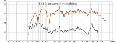
And that doesn't really match his measurement at all. (The measurement appears to have 10 db per division.)

Why? It's a terribly sloppy sim with a lot of dimensional errors and he didn't measure the driver t/s, he pulled them straight off the data sheet. Fixing the dimensional areas in Akabak with a LOT of segments won't make a whole lot of difference, so the reason the sim doesn't match the measurements is either due to t/s parameters or measurement procedure and equipment.
For all intents and purposes Cowan's Akabak sim is close enough for these purposes, despite being riddled with dimensional areas and hobbled by unmeasured t/s parameters. Yours however, with the 151.2 sq cm closed end isn't even close.
So let's throw the Dayton 315 HF into Cowan's sim and see what happens.
An externally hosted image should be here but it was not working when we last tested it.
While this may not look dramatically different than your sim, the closed end cross sectional area is about 2x larger, that has huge implications in things like compression ratio.
In some ways this is a good design, namely it's undamped response indicates the box is a good size and the design will handle power compression reasonably well. In other ways it's a terrible design, namely the massive dip at 90/100 hz as confirmed by the sim AND Cowan's own measurement.
Last edited:
I found an AR sub at the local charity store. Paired with the odds-and-ends I put together for my vacation condo, I thought the bass was absolutely fabulous - just as you think yours is. Esp. for organ and the double-basses on Diana Krall. Wow*.
.... until I ran measurements.
How about one little frequency run for us to see (with distortion, of course) of your 30 Hz TH? Software REW is honorware and mics are cheap.
Ben
*I think it must be the 90% distortion at 48 Hz that I loved so much. There's so little content down low that folks are forever accepting strong output down to 45 Hz as great bass. Which it is for the vast percentage of music.
As measured that thing can't even do the 32 hz note, much less the 16 or 8 hz organ notes so I'm not sure why you would think it was anything other than junk for organ music.
Regardless, OP's in room measurement won't tell anyone anything except how it should be eq'ed in the room it's in. Much better would be to see outdoors measurements done properly. That would be greatly meaningful as opposed to almost completely useless in room data.
That helps me understand anything wrong I might have done in hornresp. Besides leaving it the way it is, the main reason this concerns to me is because I might cut out (part of) the back to extend it accordingly. I plan to cross it over at 80hz.
Yes, this would be exactly what I plan to do, especially since I will be using it both indoors and out.Much better would be to see outdoors measurements done properly. That would be greatly meaningful as opposed to almost completely useless in room data.
While this may not look dramatically different than your sim, the closed end cross sectional area is about 2x larger, that has huge implications in things like compression ratio.
Since S1 is so small, I've considered removing the back panel and expanding it out a few inches. I just don't know how much since the sims all seem to be wrong, if someone can determine even a simple baseline that improves the compression ratio please help. This is an option I'm able to do, but so is buying another driver.
If purchasing another driver could also fix it, I'd more than gladly do it. I hope the sims aren't so far off that results are terribly false because I modeled the B&C 12PLB76 and B&C 12PLB100 with very nice results:

Max power at 7mm listed xvar (5mm xmax)
B&C 12PLB100

I know this thread is a little old, but I desperately want a solution to this.
Last edited:
if someone can determine even a simple baseline that improves the compression ratio please help. This is an option I'm able to do, but so is buying another driver.
You built Cowan's 30 hz tapped horn right? Unless you did it dramatically different than the plans there's nothing wrong with the compression ratio. It's actually pretty low.
The problem, as I pointed out in post 9, is your sim inputs. Your dimensions are WAY off. Here's a direct quote from post 9.
This is a DIRECT TRANSLATION of Cowan's 30 hz horn Akabak sim into Hornresp including the 830500 t/s parameters.
An externally hosted image should be here but it was not working when we last tested it.
For all intents and purposes Cowan's Akabak sim is close enough for these purposes, despite being riddled with dimensional areas and hobbled by unmeasured t/s parameters. Yours however, with the 151.2 sq cm closed end isn't even close.
So let's throw the Dayton 315 HF into Cowan's sim and see what happens.
An externally hosted image should be here but it was not working when we last tested it.
While this may not look dramatically different than your sim, the closed end cross sectional area is about 2x larger, that has huge implications in things like compression ratio.
See where I added bold? I TOLD YOU your Hornresp inputs were wrong and I even posted a screenshot of Cowan's own inputs (from his Akabak sim). And yet you are STILL using the wrong dimension inputs in your sim. So I'm not really sure what you are trying to ask. But your sim dimensions are wrong.
Last edited:
I just said CR because you mentioned it, but all I am referring to is general performance, it sounds way off. Not even CLOSE to either of the sims, as if it's far below the quarter wavelength fundamental or something and it's way too much for the driver.
Here's the quote from his page: "Anyone who wants to make a great little tapped horn similar to this one should make a few changes. The slope of the baffle should be increased so that the throat end measurement is 48mm, giving a 150cm^2 throat."
Now unless you've already considered I was using the 48mm version, it seems the dimensions aren't wrong.
Wrong compared to what? I understand if you thought I were using his first mentioned design, but I'm not. I've mentioned this before, but the version I used has a 48mm gap. The 30hz enclosure he first shows and the one you repeatedly referenced has a 100, but he calls for 48mm to anyone building one themself.But your sim dimensions are wrong.
Here's the quote from his page: "Anyone who wants to make a great little tapped horn similar to this one should make a few changes. The slope of the baffle should be increased so that the throat end measurement is 48mm, giving a 150cm^2 throat."
Now unless you've already considered I was using the 48mm version, it seems the dimensions aren't wrong.
Last edited:
Yes, I did miss that, so to be clear I was wrong. I probably missed it because you just said "Cowan said to do this" without showing a plan or referencing the fact that this was different from the official plans, I didn't reference what he said to do with the pics, plans and the Akabak sim, which all indicate 100 mm, not 48.
So yeah, my sim is wrong.
Your sim is showing less than 3:1 compression ratio, so that's not terrible. I wouldn't go cutting the box apart and building a "wart" on the back to fix that.
When you say "it sounds way off" unfortunately that means nothing to me. Do you have a measurement? Does it sound way off inside or outside? is it room modes or is the frequency response something you don't like? Are the high notes too much or the low notes? Does it sound "mushy" in the low notes? Is it hitting excursion limits too soon? Are you able to fix it with eq and if so what settings are you using to fix it?
See what I mean? I have no idea what you mean when you say "sound way off". There's nothing that can really be recommended based on a subjective description that doesn't really describe anything.
I'd like help but need more details. if you haven't listened to it outside or in another room or even a different spot in a different room you don't really know if the room or the enclosure is the problem.
Last edited:
I just said CR because you mentioned it, but all I am referring to is general performance, it sounds way off. Not even CLOSE to either of the sims, as if it's far below the quarter wavelength fundamental or something and it's way too much for the driver.
Are you filtering it to play only below 80 Hz? If not, then those out-of-band peaks above 100 Hz could make it sound pretty awful.
If you are filtering it, then try to measure the impedance curve and compare it to the Hornresp sim. If it's off, then there's something wrong with the build. A WT3 or DATS can do the measurement in seconds. If you don't have that, you could use REW(free) and a DIY jig (Google it) to measure the impedance curve.
Good info Brian, I might just take some time and build it. Yes, I've been using it crossed at and below 80hz with a 24 dB/octave slope. I actually simmed about 25 other drivers and found this one has the best impedance almost over all of them, the only two that significantly have nicer FRs are the two above! Currently the box is in another state, I'm out on vacation now so it'll have to wait. I'll see how it goes
That's a biiiiiiiiiiiiiiiiiiiiiiiiiiiiiiiiiiiiiiiiiiig box.
Smaller than the DTS-20! http://www.danleysoundlabs.com/danley/wp-content/uploads/2012/04/DTS-20-spec-sheet.pdf
Although the box is 185cm tall, it only weighs about 73kg. So anyone tall enough can lift it standing up without trouble. Laying on it's side under a projector screen in a dark room, it's unnoticeable.
Although the box is 185cm tall, it only weighs about 73kg. So anyone tall enough can lift it standing up without trouble. Laying on it's side under a projector screen in a dark room, it's unnoticeable.
Last edited:
- Status
- This old topic is closed. If you want to reopen this topic, contact a moderator using the "Report Post" button.
- Home
- Loudspeakers
- Subwoofers
- I built Cowan's 30Hz Tapped horn