I'm biased of course, but a long, well-stuffed pipe is like the opposite of a tapped-"horn".
With a pipe, you can stick almost any driver with a low resonance at the bottom and the pipe mightily damps the driver and the sounds coming from either end. That highly desirable "aperiodic" performance contrasts with the multi-resonant impedance curve you provided.
Still looking forward to your near-field distortion plot. Nice to see measurements well below the max of the speaker so they represent more realistic listening conditions. No need for an SPL meter unless you are in a car-audio competition.
Thanks for posting data. Brave. Good.
B.
It's easier to compare the impedance curves if you export them from Hornresp (for the sim) and DATS (as measured), then import them into REW for comparison purposes.
Having said that, don't worry too much about the level of the peaks. The Hornresp simulation doesn't take box losses into account, and the more the actual box losses, the lower the peaks will be compared to the sim. What I do sometimes is add a tiny bit of theoretical fill to the Hornresp sim to roughly simulate box losses. This brings down the level of the impedance peaks, and brings them closer in line with what's measured. I suspect that the sim'd FR would be closer to measured FR as well.
When doing impedance measurements, check to see if the dips are where they are supposed to be (the minimum points in the dips should be a good match for the minimum impedance points in the sim) and that there are no additional peaks in the impedance, or that the peaks aren't degraded, which would suggest that panel resonances are impacting the performance of the speaker.
See here for more information: The Subwoofer DIY Page v1.1 - Projects : Using Impedance Graphs

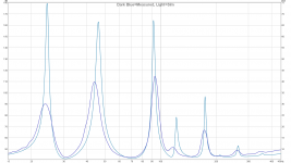
Pink is simulated (no filling added), blue is measured:

That's pretty decent correlation. Looks like the resonance frequency might be slightly higher than Hornresp predicted (all of the peaks seem to be shifted upwards in frequency a little), and the peak just above 100 Hz is a bit degraded, a possible sign of some panel flex, but it looks pretty decent.
As you have an impedance meter, try doing the sim again using the semi-inductance method (check the Hornresp thread for more details). You might find even better correlation between sim'd and measured performance (both FR and impedance).
I have DATS, can you extrapolate semi-inductance from that? GM, my inputs are post #4 and #13. Here is my record that contains my measured FP 12RS550.
You can use DATS to save the impedance curve for the driver as a ZMA file. Use the semi-inductance spreadsheet provided in the Hornresp thread and that ZMA file to generate the additional semi-inductance parameters.
Double click on the 'Le' and it should turn red. Your sim will look quite different  .
.
Note that in HR HELP is a File/Find that allows you to quickly zero in on what you want.
Re your actual build........you used the smaller throat and apparently the same end point of the divider board and further that it's a rectangle with nominally the same width, ergo S4 must be much larger than Cowan's 945 cm^2. Just doing a quickie estimate to match net Vb I got 1133 cm^2, but would be nice to get a proper measurement.
GM
.Note that in HR HELP is a File/Find that allows you to quickly zero in on what you want.
Re your actual build........you used the smaller throat and apparently the same end point of the divider board and further that it's a rectangle with nominally the same width, ergo S4 must be much larger than Cowan's 945 cm^2. Just doing a quickie estimate to match net Vb I got 1133 cm^2, but would be nice to get a proper measurement
.GM
Thank you Brian for doing the spreadsheet work to figure out the Semi-Inductance specs of these drivers. Measured mouth area is 945 square CM. Here are simulations vs overlays with my Faital Pro 12RS550 and my B&C 12PLB100. Faital Pro:

Group delay:

B&C 12PLB100 and doppler shift (probably from a plane) around 68-73Hz:


Here are the advanced thiele-small parameters for my two drivers if anybody wants to use them:
Group delay:
B&C 12PLB100 and doppler shift (probably from a plane) around 68-73Hz:
Here are the advanced thiele-small parameters for my two drivers if anybody wants to use them:


One thing I should mention to anyone wanting to build this: Route out the corners on the inside of the mouth because I notice a high frequency sound from turbulence. I would in fact refold the entire horn using Brian's Boxplan-SS w/ optimization to have a larger mouth (or at least get rid of that immediate 90 degree turn) because chuffing is the problem with this horn.
Last edited:
- Status
- This old topic is closed. If you want to reopen this topic, contact a moderator using the "Report Post" button.
- Home
- Loudspeakers
- Subwoofers
- I built Cowan's 30Hz Tapped horn