I found a great deal on some 12" subwoofer drivers, so I bought a bunch (12 of them to be exact). I'm using them to build a 12-driver dipole subwoofer that will be eventually used in conjunction with some open baffle 3-way speakers. I plan to crossover to the sub around 80-100Hz depending on where in frequency the first dipole peak is located.
The design is a new twist on existing themes, although it's nothing all that innovative. I like to think of it most simplistically as a U-frame or an H-frame that has a longer "line" to the rear compared to the front. In order to fit all 12 drivers in a small space they are nested one on top of the next. This creates a cavity and is similar to the dipole subwoofer that Siegfried Linkwitz used in his Phoenix project a few years back, although my design has additional line length to the back. In some ways it is like Nelson Pass' "Slot Loaded" open baffle, except its a slot loaded U-frame. Some of the same resonance issues (related to the cavity depth) of that design will be present in this one. My design also has some relationship to the Ripole (with the addition of the rear line), since the close nesting results in openings to the front and rear that are equal to about 0.4*Sd for each driver. As a result, I expect that the resonance frequency will lower and Q will increase compared to the free-air values.
The overall dimensions of the enclosure are about 18"H, 60"W, and 30" deep. The cabinet will be used horizontally, like a bulky AV cabinet or credenza thingy. This will be located between the main speakers.
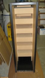
So far I have built the outer cabinet and cut wood to form the inner dividers that direct the radiation to the front and rear. Below are a couple of pics taken while I was dry fitting the interior pieces. I have decided to glue everything together, although this will mean that I will likely never be able to take the sub apart without damaging the drivers unless I am able to get creative and carefully saw everything apart like a surgeon while at the same time not creating any dust... Since I am a terrible woodworker I used some inexpensive and lightweight honeycomb panels for the exterior shell from my favorite local supplier, IKEA. Even so, after I add the interior wood and all 12 drivers the weight will probably be over 100 pounds. Hopefully it will turn out to be sufficiently mechanically rigid and strong to not snap in half when looking at it cross-eyed.
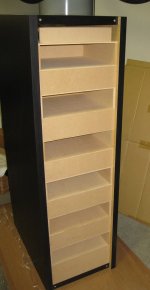
In the attached pics the cabinet is standing upright, however, this is just for the moment and done out of convenience. In this orientation all the drivers would be facing the ceiling and this might cause cone sag and increase distortion a bit. When it is in use the cabinet will be oriented horizontally and the axis of the cone motion will be parallel to the floor. The left picture is a view from the rear and the right is looking at the front. In each cavity there will be the magnet of one driver nesting into the cone of another. Drivers will operate in push-pull within each cavity, which should cancel some even order distortion products.
The design is a new twist on existing themes, although it's nothing all that innovative. I like to think of it most simplistically as a U-frame or an H-frame that has a longer "line" to the rear compared to the front. In order to fit all 12 drivers in a small space they are nested one on top of the next. This creates a cavity and is similar to the dipole subwoofer that Siegfried Linkwitz used in his Phoenix project a few years back, although my design has additional line length to the back. In some ways it is like Nelson Pass' "Slot Loaded" open baffle, except its a slot loaded U-frame. Some of the same resonance issues (related to the cavity depth) of that design will be present in this one. My design also has some relationship to the Ripole (with the addition of the rear line), since the close nesting results in openings to the front and rear that are equal to about 0.4*Sd for each driver. As a result, I expect that the resonance frequency will lower and Q will increase compared to the free-air values.
The overall dimensions of the enclosure are about 18"H, 60"W, and 30" deep. The cabinet will be used horizontally, like a bulky AV cabinet or credenza thingy. This will be located between the main speakers.
So far I have built the outer cabinet and cut wood to form the inner dividers that direct the radiation to the front and rear. Below are a couple of pics taken while I was dry fitting the interior pieces. I have decided to glue everything together, although this will mean that I will likely never be able to take the sub apart without damaging the drivers unless I am able to get creative and carefully saw everything apart like a surgeon while at the same time not creating any dust... Since I am a terrible woodworker I used some inexpensive and lightweight honeycomb panels for the exterior shell from my favorite local supplier, IKEA. Even so, after I add the interior wood and all 12 drivers the weight will probably be over 100 pounds. Hopefully it will turn out to be sufficiently mechanically rigid and strong to not snap in half when looking at it cross-eyed.
In the attached pics the cabinet is standing upright, however, this is just for the moment and done out of convenience. In this orientation all the drivers would be facing the ceiling and this might cause cone sag and increase distortion a bit. When it is in use the cabinet will be oriented horizontally and the axis of the cone motion will be parallel to the floor. The left picture is a view from the rear and the right is looking at the front. In each cavity there will be the magnet of one driver nesting into the cone of another. Drivers will operate in push-pull within each cavity, which should cancel some even order distortion products.
Attachments
Pretty clever way to use a lot of drivers. The total cone area should be equivalent to about 5.3 18" drivers, since 18s are a pretty easy to visualize metric of driver size. I'm very eager to see the measurements if you can produce some.
I've always somewhat wondered how well that kind of dipole design really works for subs.
My intuition is never really satisfied that the front and back are both open. Then again I am one of those electronic high spl sub junkies. 6th order resonant systems are my thing.
I've always somewhat wondered how well that kind of dipole design really works for subs.
My intuition is never really satisfied that the front and back are both open. Then again I am one of those electronic high spl sub junkies. 6th order resonant systems are my thing.
Curious to hear how it turns out. Will you be taking measurements & posting them ?
Yes. Give me a chance to finish building it first!
")
Pretty clever way to use a lot of drivers. The total cone area should be equivalent to about 5.3 18" drivers, since 18s are a pretty easy to visualize metric of driver size. I'm very eager to see the measurements if you can produce some.
I've always somewhat wondered how well that kind of dipole design really works for subs.
My intuition is never really satisfied that the front and back are both open. Then again I am one of those electronic high spl sub junkies. 6th order resonant systems are my thing.
These particular drivers work well for close nesting because the magnet is not all that large and the dustcap is the inverted variety. If you touch the back edge of the magnet of one driver to the cone of the next the distance is only 3.5 inches (although this would not allow any cone movement). I am using a spacing of about 4.25", which would allow for up to ~20mm of cone movement (Xmax is 8.5mm). This allows me to pack quite a few drivers in a relatively small space.
I recall listening to some large open baffle DIY dipoles that used three 18" low-Xmax drivers. These were playing some carousel organ music, and the bass was quite impressive. In my design the upper end will be strictly limited to around 80-100Hz, however, the dipole loss at the lowest frequencies will not be as severe as some other systems.
In any case, the number of drivers used is not any kind of effort to make a high SPL system. I am only trying to make up for the losses that the dipole loading will create.
Charlie you better bring these beasts to Burning Amp!
See:
http://www.diyaudio.com/forums/clubs-events/277751-burning-amp-2015-schedules-info.html#post4405640
If anyone's in socal, heres a couple of ideas:
1) go to apex Jr and pick up a dozen of the cerwin Vega twelves. For $264 you'll have more displacement than four eighteens.
Or
2) check out the Alpine sws-15. It'll need some power to get loud, but there aren't many drivers with more displacement at the price. I paid something like $125. A lot of car stereo shops sell this driver.
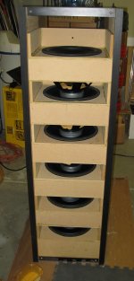
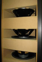
After a bunch of routing, gluing, screwing, then yet more gluing, and gluing, and gluing, I have about 85% of the assembly completed. See attached pics for evidence of this. I still need to glue the last driver into place but I ran out of glue so I'm all done for today. I need to cut a couple last pieces once I know the dimensions of the last cavity.
In the pics you can see the assembly and a closeup showing the nesting of the drivers. Not shown is the rear view with lots of dangling wires that will eventually be connected in three parallel banks of four drivers in series. If I believe the datasheet sensitivity numbers, this arrangement will end up around 4.5 Ohms (DC impedance) with a voltage sensitivity of about 97dB@2.83v. Not bad.
In the pics you can see the assembly and a closeup showing the nesting of the drivers. Not shown is the rear view with lots of dangling wires that will eventually be connected in three parallel banks of four drivers in series. If I believe the datasheet sensitivity numbers, this arrangement will end up around 4.5 Ohms (DC impedance) with a voltage sensitivity of about 97dB@2.83v. Not bad.
Attachments
You still haven't said what the drivers are ?
Following
Here's a link to the drivers I am using:
GRS 12SW-4 12" Poly Cone Subwoofer 4 Ohm
Less than $20 each if you buy at least four (why not?). I tested each of them for TS parameters and they were all very close to the MFG specs. In total, the drivers cost less than $250, including shipping.
Last edited:
With a Qts of .98 they should work very well in your OB cab. Can you measure them when they are complete?
sent from cell
Yes, unless the Q increases a lot due to loading by the cavities these should work very well for this project.
I always try to use measurements, however, in this case I won't be able to make direct free-field or even quasi-free-field measurements. Instead, I will make a near field measurement at the front opening and another at the back opening, and then combine them with the rear response having both inverted polarity and delay that corresponds to the pathlength difference. The result will be the free-field frequency response on axis.
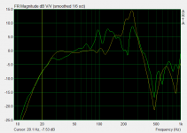
I managed to finish the assembly today. After connecting the wiring and doing some initial checks I took some measurements. These are attached (attachment at left). The measurements are of the front (orange) and rear (green) output, with the rear SPL level adjusted to account for the larger open area. I have also moved the front passband response to about 0dB as a guide for the eye since levels are only relative.
There are definitely some resonances present. The "slot" cavity resonance can clearly be seen in the front response, peaking at about 250 Hz. Since this doesn't really start until about 100Hz (the upper edge of the passband) I am not too concerned about it. In the rear response I believe there are two different resonances present. The peak at 250Hz is still there, but below part of it is missing and there is some peaking around 100Hz. I think the lower resonance is being produced by the large rear cavity and this has a null around 200Hz, which cancels part of the cavity resonance. Interesting stuff.
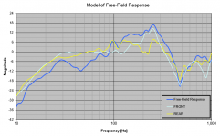
The near field front and rear measurement data can be combined to model the free-field response. I did this in the Active Crossover Designer, and the result is included as the second attachment. The cyan and yellow traces are the front and rear responses, as before, and the dark blue trace is the combined response with the rear response inverted and delayed following the acoustics properties and dimensions of the dipole design. Because of the various resonances the combined response has some peaks and dips, e.g. at 45Hz. I plan to fill this in using EQ and flatten the response overall as part of the crossover. I'm surprised that the low end does not roll off more (from the dipole cancellation) but this is just how the data plays out. In general the response has the characteristic 6dB fall in SPL per octave below about 150-200Hz or so as you would expect.
There are definitely some resonances present. The "slot" cavity resonance can clearly be seen in the front response, peaking at about 250 Hz. Since this doesn't really start until about 100Hz (the upper edge of the passband) I am not too concerned about it. In the rear response I believe there are two different resonances present. The peak at 250Hz is still there, but below part of it is missing and there is some peaking around 100Hz. I think the lower resonance is being produced by the large rear cavity and this has a null around 200Hz, which cancels part of the cavity resonance. Interesting stuff.
The near field front and rear measurement data can be combined to model the free-field response. I did this in the Active Crossover Designer, and the result is included as the second attachment. The cyan and yellow traces are the front and rear responses, as before, and the dark blue trace is the combined response with the rear response inverted and delayed following the acoustics properties and dimensions of the dipole design. Because of the various resonances the combined response has some peaks and dips, e.g. at 45Hz. I plan to fill this in using EQ and flatten the response overall as part of the crossover. I'm surprised that the low end does not roll off more (from the dipole cancellation) but this is just how the data plays out. In general the response has the characteristic 6dB fall in SPL per octave below about 150-200Hz or so as you would expect.
Attachments
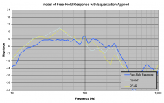
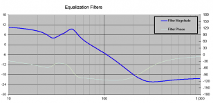
After playing around a little while I think I have figured out a set of EQ filters that I could use to flatten the response and make it useful. It's definitely not the standard 6-dB-per-octave boost on account of the various resonances involved, but it does flatten the bass response nicely. The low end extends to about 25Hz after applying the EQ (according to my model).
See attached pics of models of EQ'd subwoofer response and the EQ filter used to generate it.
See attached pics of models of EQ'd subwoofer response and the EQ filter used to generate it.
Attachments
What are your impressions? I'm kindof curious what the strong and weak points of this design would be.
Is it more effective than buying a single woofer of comparable price and dropping it in a large ported box? Say something like Dayton Audio RSS460HO-4 18" Reference HO Subwoofer 4 ohm
Is it more effective than buying a single woofer of comparable price and dropping it in a large ported box? Say something like Dayton Audio RSS460HO-4 18" Reference HO Subwoofer 4 ohm
- Status
- This old topic is closed. If you want to reopen this topic, contact a moderator using the "Report Post" button.
- Home
- Loudspeakers
- Subwoofers
- Twelve 12" driver dipole subwoofer build thread