Hi DIY audio crew,
I have an old active 10" ported subwoofer in my music set up whose cabinet is getting a bit rattly in its old age- it also suffers from port chuff at higher volumes. I have been able to get the Thiele small parameters for the driver that was used in it and have been contemplating experimenting with a new enclosure to see what performance gains can be made by recycling the amp and driver but making a new cabinet. I have recently been able to spend some time wrapping my head around horn resp and sketch-up and have a first draft of sorts for a tapped horn cabinet for the driver. I am looking for someone to maybe check my working/ modelling to make sure i have not made any critical mistakes before going out and making sawdust (I am more of a carpenter than I am an audio designer!)
First things first, the sub uses a plate amp that has high and low pass filters at 40hz-160hz. Given that I have pretty good floorstanders with decent bass extension I plan on using the cabinet for 40-100hz. I have been reading quite a lot of threads here and on the AVS forums about modelling tapped horns and think I have got the basics down.
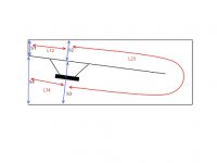
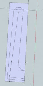
A few things that I am unsure of- I used a diagram from an AVS thread by lilmike to help explain what the s1, s2, s3, s4 L12, L23, L34 values mean in relation to a tapped horn enclosure. For my design I want to have a tall, narrow tower with the mouth firing out the front panel at the bottom instead of the pipe style indicated in lilmikes diagram. I am unsure how that affects S3, S4 and L34 values. In my Sketch up design I have been able to fold the horn so that the horn length, and mouth size are the same values (even if their location is different). Can anyone spot any issues i might have with my proposed design?
In my sketch up I have not allowed for panel width just yet as I am unsure what ply/mdf I will be able to get my hands on (I am currently based in Laos for the next few years). Once I find out what is available I can adjust the model accordingly and make some cut lists.
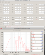
Here are the Thiele/ small parameters for the driver
FS 31.9449 Hz VAS 26.4401 L RE 4.0000
QMS 12.0403 QES 0.5091 QTS 0.4885
B×l 11.6988 T×m dBSPL 84.3091 SD 0.0257 m2
CMS 0.2860 mm/N MMS 86.7895 g RMS 1.4468 WM
CAS 1.89E-7 m5/N MAS 131.09 kg/m4 RAS 2185 WA
CMES 634.1420 mF LCES 39.1426 H RES 94.5950 W
RAT 53866 WA RMT 35.6621 WM MMD 84.4534 g
ZMIN 4.7405 W ZMAX 98.5950 W ZAVG 35.3035 W
h0 0.1625 % L1kHz 3.4342 mH L10kHz 1.5402 mH
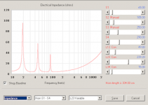
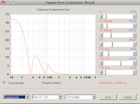
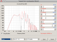
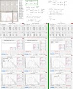
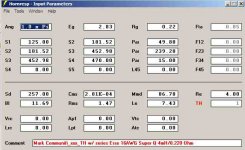
And here are some screens from my horn resp model.
Thanks for having a look. let me know if you spot anything awry! Hopefully will be able to get onto building this as soon as a design is settled on as I have a bit of free time on my hands at the moment.
Mark
I have an old active 10" ported subwoofer in my music set up whose cabinet is getting a bit rattly in its old age- it also suffers from port chuff at higher volumes. I have been able to get the Thiele small parameters for the driver that was used in it and have been contemplating experimenting with a new enclosure to see what performance gains can be made by recycling the amp and driver but making a new cabinet. I have recently been able to spend some time wrapping my head around horn resp and sketch-up and have a first draft of sorts for a tapped horn cabinet for the driver. I am looking for someone to maybe check my working/ modelling to make sure i have not made any critical mistakes before going out and making sawdust (I am more of a carpenter than I am an audio designer!)
First things first, the sub uses a plate amp that has high and low pass filters at 40hz-160hz. Given that I have pretty good floorstanders with decent bass extension I plan on using the cabinet for 40-100hz. I have been reading quite a lot of threads here and on the AVS forums about modelling tapped horns and think I have got the basics down.
A few things that I am unsure of- I used a diagram from an AVS thread by lilmike to help explain what the s1, s2, s3, s4 L12, L23, L34 values mean in relation to a tapped horn enclosure. For my design I want to have a tall, narrow tower with the mouth firing out the front panel at the bottom instead of the pipe style indicated in lilmikes diagram. I am unsure how that affects S3, S4 and L34 values. In my Sketch up design I have been able to fold the horn so that the horn length, and mouth size are the same values (even if their location is different). Can anyone spot any issues i might have with my proposed design?
In my sketch up I have not allowed for panel width just yet as I am unsure what ply/mdf I will be able to get my hands on (I am currently based in Laos for the next few years). Once I find out what is available I can adjust the model accordingly and make some cut lists.
Here are the Thiele/ small parameters for the driver
FS 31.9449 Hz VAS 26.4401 L RE 4.0000
QMS 12.0403 QES 0.5091 QTS 0.4885
B×l 11.6988 T×m dBSPL 84.3091 SD 0.0257 m2
CMS 0.2860 mm/N MMS 86.7895 g RMS 1.4468 WM
CAS 1.89E-7 m5/N MAS 131.09 kg/m4 RAS 2185 WA
CMES 634.1420 mF LCES 39.1426 H RES 94.5950 W
RAT 53866 WA RMT 35.6621 WM MMD 84.4534 g
ZMIN 4.7405 W ZMAX 98.5950 W ZAVG 35.3035 W
h0 0.1625 % L1kHz 3.4342 mH L10kHz 1.5402 mH
And here are some screens from my horn resp model.
Thanks for having a look. let me know if you spot anything awry! Hopefully will be able to get onto building this as soon as a design is settled on as I have a bit of free time on my hands at the moment.
Mark
Attachments
Thanks for the tips so far. Horn segments have been changed to Parabolic with little/no real change to the results at an initial glance. Thanks for the pick up Brian.
@ Sine143- Originally L12 was much shorter but there was a trough in the passband of around 4db. By making L12 longer in relation to L34 I could flatten it out to the few db that you see in the current FR chart. I did make it even longer so that the cabinet would be easy to make/fold. The huge drop off at 100hz should not be an issue if i have the crossover at 80-90hz right? That is the current setting I have with my sub in the system and anticipate it will stay the same. I may be wrong on that though!
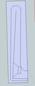
I'll attach a new sketch up with the driver position/ throat better marked out.
@ Sine143- Originally L12 was much shorter but there was a trough in the passband of around 4db. By making L12 longer in relation to L34 I could flatten it out to the few db that you see in the current FR chart. I did make it even longer so that the cabinet would be easy to make/fold. The huge drop off at 100hz should not be an issue if i have the crossover at 80-90hz right? That is the current setting I have with my sub in the system and anticipate it will stay the same. I may be wrong on that though!
I'll attach a new sketch up with the driver position/ throat better marked out.
Here is the sketch up pic with driver included. I realise it may have been confusing initially as I have drawn in the horn path to help me when working with Horn Resp (it may look like an interior baffle). The horn mouth is indicated by the extra lines out to the right.
Quick question about compression ratios. Currently mine is at 2.45:1. Any issues with that value?
Thanks for the help!
Mark
Quick question about compression ratios. Currently mine is at 2.45:1. Any issues with that value?
Thanks for the help!
Mark
Attachments
Last edited:
The huge drop off at 100hz should not be an issue if i have the crossover at 80-90hz right?
The huge notch can make it hard to get a good crossover transition. Even with the low pass filter in place there's still going to be a massive notch in your response when you add in the mains. You can simulate the crossover with a different program. and you will see there's no way to fix that huge hole in response. You can ignore it and it might not bother you but you'll never have anything approaching flat response through that region.
Thanks 'Just a guy'. I do not want to end up with a big hole in my response at the crossover frequency. I am not sure what the standard crossover slope is on the plate amp that I have but it sure is unlikely to be anything like what my initial FR chart would require.
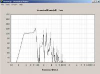
For your consideration is the previous FR chart (with bigger db variation in the pass band but with a much less severe roll off around the 100hz mark). The old chart is in grey, the new in red.
Any thoughts on how i could flatten the response in the pass band without resulting in a huge drop off at 100hz?
Sine143 mentioned the driver would be better suited to a FLH cabinet. That is new territory for me as although i've built them before, I have not had to model them. The tapped horn is a very simple and quick build- which is a plus for me given my limited tools on hand....
choices, choices
Attachments
Shortening L12 will bring the upper band sensitivity up and adjusting the length of the last segment will make the dip on either side of the 150 hz peak move up or down. You can have a bigger dip on the 130 hz side or on the 180 hz side, or you can make them equally deep dips.
Front loaded horn is not really any more complicated than tapped horn, just add a chamber to the sim and to the build. Here's an ultra simple recent example, it's almost exactly the same as your plans but with a chamber added to the top of the box.
"The Sublimator" An Infinity 1260w 18hz Tuned Offset Driver Folded Horn. - AVS | Home Theater Discussions And Reviews
Hi Y'all,
Don't wory too much about the steep dip above the passband. IIRC Volvotreter build a very similar looking TH that turned out well.
Tapped Horns
Try using some light filling in the Hornresp Wizard around the driver area, and then go into the Active Filter Wizard. I found a 2nd order HP @ 40Hz and a 4th order LP @ 100Hz get rid of most of the problems.
Regards,
I don't usually disagree with TB46 but I have to this time. IMO you shouldn't have deep dips anywhere near the passband especially if they can be avoided simply and easily.
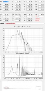
Your second sim was a lot better than the first one, precisely because you shortened L12. Big improvement. Here's one extra tweak, changing L34 and now the dip is almost gone. If you want to get rid of that dip completely you need a different driver. A complete redesign might be able to help a bit but the driver is holding you back from a less dipped response.
(Your original design response is overlaid in blue.)
When it's that easy to improve that much it's probably worth it to do it.
Another couple things I noticed - your sim is .5 pi, that's a bit optimistic even if you plan to corner load the sub. It's usually best to stick to 2 pi for open space, or 1 pi for a more accurate picture of corner loading unless your walls are thick concrete.
Also that driver has freakishly high inductance for an 11 mm xmax driver. (I assume it's 11 mm because that's what you showed it at in your sim.) Due to the high inductance it's unlikely your sim is going to match reality no matter what you do with it unless you tweak the sim to adjust for inductance. Adjusting for inductance is going to make your sim look worse. If you don't adjust a measurement of the finished product won't match the sim.
Your second sim was a lot better than the first one, precisely because you shortened L12. Big improvement. Here's one extra tweak, changing L34 and now the dip is almost gone. If you want to get rid of that dip completely you need a different driver. A complete redesign might be able to help a bit but the driver is holding you back from a less dipped response.
(Your original design response is overlaid in blue.)
An externally hosted image should be here but it was not working when we last tested it.
When it's that easy to improve that much it's probably worth it to do it.
Another couple things I noticed - your sim is .5 pi, that's a bit optimistic even if you plan to corner load the sub. It's usually best to stick to 2 pi for open space, or 1 pi for a more accurate picture of corner loading unless your walls are thick concrete.
Also that driver has freakishly high inductance for an 11 mm xmax driver. (I assume it's 11 mm because that's what you showed it at in your sim.) Due to the high inductance it's unlikely your sim is going to match reality no matter what you do with it unless you tweak the sim to adjust for inductance. Adjusting for inductance is going to make your sim look worse. If you don't adjust a measurement of the finished product won't match the sim.
Last edited:
PS: Agree with TB46
About what? You just showed the first design requires a 48 db highpass on the mains for a smooth crossover point. That isn't standard issue equipment. His plate amp very likely has a 12 db built in highpass, 24 db is the steepest I've ever seen in a plate amp. So how is he going to get anything resembling a smooth crossover transition between the subs and mains? It isn't possible with the design with the massive hole at 110 hz without extra processing equipment.
If you have really fancy dsp you can make almost anything work but I don't think that's what the OP had in mind.
Don't wory too much about the steep dip above the passband. IIRC Volvotreter build a very similar looking TH that turned out well.
I've built one TH with a noticeable dip and one without. I significantly preferred the sound of the one without the dip. I wouldn't build one based on a sim that showed such a huge dip so close to the passband.
Btw, an aboUT 60 liter flh has almost identical sensitivity, with a big peak around 120hz (but no dip). Only difference is the placement of the excursion minimas. In my opiniom, it is superior if you are running with no eq. WITH eq, you can add some boost at 35 hz to extend the low corner in the taped horn, as that is the excursion minima (but you've got a big excursion spike in the middle of your passband around 50hz. The flh had the minima at 50hz, meaning your hipass filter is the only thing needed to keep excursion under control
Last edited:
Many thanks for your input folks. I currently do not have an advanced DSP crossover system in place so am relying on the Plate amp (unsure of the slope). I am looking at going down the minidigi/2x4 mini dsp down the track but won't rely on it for this project- hence I think i'll be looking to minimize any steep troughs/spikes by virtue of the cabinet design and not electrical wizardry.
@ TB46- I had seen that website before but had forgotten about it until you sent the link! Interesting to see that we came up with the same scheme to flatten out response in the passband (extend L12 in relation to L34). He mentioned with his design that he included a 4,7mh coil (1,32mm dia. copper wire with a Rdc of 0,26 ohm) to assist with flattening out the response. Can anyone enlighten me as to the process by which this occurs?
@sine143- interested to look at the FLH alternative you mentioned. Any clues as how to determine the best volume of the reach chamber? Any rules of thumb I should get to know?
Hopefully I'll be able to get onto making something next week if i can settle on a design.
Cheers!
Mark
Had a quick fiddle with Horn resp for a FLH of similar size. Response is almost identical except the response dip at around 130hz is replaced with a similar sized spike. If there is no benefit in terms of crossing over between these two options i think i'll go with the tapped horn for ease of construction... Unless anyone more knowledgeable can sway me otherwise ")
Hi Mark,
Post #16: "...He mentioned with his design that he included a 4,7mh coil (1,32mm dia. copper wire with a Rdc of 0,26 ohm) to assist with flattening out the response. Can anyone enlighten me as to the process by which this occurs?"
A coil in series w/ the driver is a 1st order LP filter.
In modelling a loudspeaker/driver system the drivers Le and Re are ususally placed in series w/ the power source (amplifier). In Hornresp you'll also find Rg (amplier output resistance).
When you add a series inductor in Hornresp the inductance will be added to Le, and the resistance of the coil (DCR) is added to Rg.
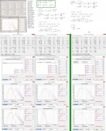
You don't need a coil for your design. I'll attach a Hornresp simulation for your driver w/ larger cross-sections (same lengths) that could benefit from a series inductor. EXAMPLE ONLY!
For the home this is a valid approach, as Danley showed in his DTS-20. The Erse Super Q coils w/ 16AWG wire are suitable for this purpose (see: PartsExpress).
For PA applications the amount of heat generated in the series resistance, and through eddy currents in the core, will require very heavy wire wound on a transformer style iron core. Most would consider this not cost effective.
Regards,
Post #16: "...He mentioned with his design that he included a 4,7mh coil (1,32mm dia. copper wire with a Rdc of 0,26 ohm) to assist with flattening out the response. Can anyone enlighten me as to the process by which this occurs?"
A coil in series w/ the driver is a 1st order LP filter.
In modelling a loudspeaker/driver system the drivers Le and Re are ususally placed in series w/ the power source (amplifier). In Hornresp you'll also find Rg (amplier output resistance).
When you add a series inductor in Hornresp the inductance will be added to Le, and the resistance of the coil (DCR) is added to Rg.
You don't need a coil for your design. I'll attach a Hornresp simulation for your driver w/ larger cross-sections (same lengths) that could benefit from a series inductor. EXAMPLE ONLY!
For the home this is a valid approach, as Danley showed in his DTS-20. The Erse Super Q coils w/ 16AWG wire are suitable for this purpose (see: PartsExpress).
For PA applications the amount of heat generated in the series resistance, and through eddy currents in the core, will require very heavy wire wound on a transformer style iron core. Most would consider this not cost effective.
Regards,
Attachments
- Status
- This old topic is closed. If you want to reopen this topic, contact a moderator using the "Report Post" button.
- Home
- Loudspeakers
- Subwoofers
- Experiments in Tapped horns