Ok so since my designs look like a constant volume tapped horn I've begun to model them as such, Now I need to know: if my driver opening (where the magnet is) is behind the driver itself and not below like the standard tapped horn, is the "L34" referring to the distance from the mounting part of the driver or the magnet part (6 inch deep speaker makes this number vary a bit depending on interpretation). Also, I assume that I'm correct that this last section would be distance to the opening because it's basically bent 90 degrees from the simple TH example.
That's one way to do it. I just sweep the impedance curve, give like a 10-20% buffer and then use that. Most subwoofers have an impedance low spot of darn close to Re. E.G. 7.1 vs a Re of 7 for one of the designs I considered. .
Saba,
Yep , i get the same thing too, In many of my sims i am finding impedance minimums that are only a few % above the driver's RE ...... So if my driver has an RE of 5.2 i might see a minimum of 5.4 in the impedance curve .... This is with HR .... Still doesn't come close to the 8ohm that this driver's maker insists upon , but 5.4*1.4 comes pretty close, *1.5 gets us extremely close ...
Last edited:
Going to post pictures with how I understand the segments of my "TH" design. Since you mentioned the driver isn't mounted to the very end but rather to a center baffle it makes sense that I should model as a TH and use L12 as the offset of the center of the driver from the end. What I'm not sure about now is if you have that end piece in place how does that change L23 and L34. I'm kinda guessing that L23 ends at the center of the back of the driver as in Simple Tapped Horn Tutorial using Hornresp - AVS Forum
But if that's the case how is the L34 designated?
But if that's the case how is the L34 designated?
Ok so since my designs look like a constant volume tapped horn I've begun to model them as such, Now I need to know: if my driver opening (where the magnet is) is behind the driver itself and not below like the standard tapped horn, is the "L34" referring to the distance from the mounting part of the driver or the magnet part (6 inch deep speaker makes this number vary a bit depending on interpretation). Also, I assume that I'm correct that this last section would be distance to the opening because it's basically bent 90 degrees from the simple TH example.
If you are using a three segment pipe or horn L34 refers to the distance between the cone and the exit/mouth of the box .... If you are using 4 segments then L45 does the same thing .... In an end firing sort of arrangement the distance should be measured from the center of the cone (in other words if the driver is oriented with the driver diaphragm parallel to the path then half the cone's diameter has to be accounted for in L34 for three segments or L45 for four segments )
If you are using a three segment pipe or horn L34 refers to the distance between the cone and the exit/mouth of the box .... If you are using 4 segments then L45 does the same thing .... In an end firing sort of arrangement the distance should be measured from the center of the cone (in other words if the driver is oriented with the driver diaphragm parallel to the path then half the cone's diameter has to be accounted for in L34 for three segments or L45 for four segments )
Got it.
Messing with tapers and unfortunately it seems to necessitate bigger boxes the more taper you use to maintain tune. I took a 3 inch deep throat to 10.5 inch deep mouth design through and it was something like a 48 Hz tune  . I'm doing my darndest to get this thing a little flatter (back to around 122 -123 average, right not it's 123.6 with a 120 dip that may or may not happen IRL).
Maybe I'm measuring the diagonal path wrong but it doesn't seem to add much, Just realized -> geometry. Need deeper box to make a tilt mean much lol.
. I'm doing my darndest to get this thing a little flatter (back to around 122 -123 average, right not it's 123.6 with a 120 dip that may or may not happen IRL).Maybe I'm measuring the diagonal path wrong but it doesn't seem to add much, Just realized -> geometry. Need deeper box to make a tilt mean much lol.
Reverse tapering (like any constriction especially close to the end of path) will help shorten the path and allow the box to be a little smaller .... Expansion does just the opposite but with the benefit of some better output (in a bigger box) .... Its just a balance of compromises really ...
You have to remember to leave yourself enough depth for the magnet to fit as well .... This is why the magnet out method is so popular in pipes/horns with expansion, not only does it allow the driver to fit but magnets in the mouth provide superior cooling of the motor ...
You have to remember to leave yourself enough depth for the magnet to fit as well .... This is why the magnet out method is so popular in pipes/horns with expansion, not only does it allow the driver to fit but magnets in the mouth provide superior cooling of the motor ...
For those who may be interested in folding this for fun. I'm going to work on a basic fold for this beast. ~7 cu. ft. internal volume, 128 dB in the power band, 2 sws 12's HP at 30 Hz. Mouth velocity is 11.75 M/s peak at full power at 36 hz. This will be end firing most likely to avoid too much air compression at the mouth.
I realized that this driver doesn't model well unless used in pairs (in a TH or by association a pipe alignment) so this is a single cabinet with the highest output to size I've seen in a while (perhaps someone knows of something even more output to size they can link). Usable to 30 Hz in a corner, flat to f3 at 33 freestanding. There is a 20% larger version that gets .7 dB more on average but I thought that's not enough to justify the size. This will likely be 18 inches deep ~48 tall 18 wide or something. Still haven't calculated anything so don't quote me on that. I'll aim to keep it to 48 for cheap wood cost. Removable back panel (or partial) is likely needed to mount the drivers here.
For reference, my 46 tall pipe design doubled up (2 woofers vs 2 woofers) is 2-3 dB less output from 45-85, with more output at 35 (althought that would most likely be EQ'ed down)),
This is 260 L internal (which because they are separate there two extra side panels worth of width that isn't looked at here -- internal volume reported).
The Horn is 200 L internal (30%less) and more output on average and wayyy flatter.
I may just have to buy me another driver...
I realized that this driver doesn't model well unless used in pairs (in a TH or by association a pipe alignment) so this is a single cabinet with the highest output to size I've seen in a while (perhaps someone knows of something even more output to size they can link
). Usable to 30 Hz in a corner, flat to f3 at 33 freestanding. There is a 20% larger version that gets .7 dB more on average but I thought that's not enough to justify the size. This will likely be 18 inches deep ~48 tall 18 wide or something. Still haven't calculated anything so don't quote me on that. I'll aim to keep it to 48 for cheap wood cost. Removable back panel (or partial) is likely needed to mount the drivers here.For reference, my 46 tall pipe design doubled up (2 woofers vs 2 woofers) is 2-3 dB less output from 45-85, with more output at 35 (althought that would most likely be EQ'ed down)),
This is 260 L internal (which because they are separate there two extra side panels worth of width that isn't looked at here -- internal volume reported).
The Horn is 200 L internal (30%less) and more output on average and wayyy flatter.
I may just have to buy me another driver...
Last edited:
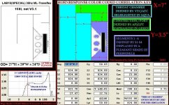
FINAL VERSION OF THE ML-TRANSFLEX FOR THE LAB15(SPECIAL)! DETAILS AND COLLAGE
Here is ML-Transflex for Lab15 (special) version 3.1
The Tapped, Squeezed and refolded remix ... better than ever ...
Ready to go shopping for ply BeauB?
Path length in this box turned out better than i thought! Width had to be increased in order to offset airspace taken up by internal panels while also maintaining path area and lengths to match the HR model, but it is all worked out now
Around 7 foot of path length with the mass loading puts our FB right at 35hz ...
If i were a salesman i suppose the selling points would be much like before and they are as follows :
(for more enjoyment just imagine the following spoken by a high energy guy with an infomercial voice and a terrible suit, because it is better that way)
If anyone makes the mistake of sending me three easy payments of 19.95 + S & H i will probably just keep the money and refer them to this post, or maybe i will send them my used "Super Shamwow", or a used food dehydrator, or a bottle of spray paint for your bald spot ........ but i am keeping the George Foreman Grill dammit! ...
Here is ML-Transflex for Lab15 (special) version 3.1
The Tapped, Squeezed and refolded remix ... better than ever ...
Ready to go shopping for ply BeauB?
Path length in this box turned out better than i thought! Width had to be increased in order to offset airspace taken up by internal panels while also maintaining path area and lengths to match the HR model, but it is all worked out now
Around 7 foot of path length with the mass loading puts our FB right at 35hz ...
If i were a salesman i suppose the selling points would be much like before and they are as follows :
(for more enjoyment just imagine the following spoken by a high energy guy with an infomercial voice and a terrible suit, because it is better that way)
- Great output and extension down to the fundamental, meets rated linear excursion of this driver right at it's thermal power rating of 600 watts! So it is very well balanced in terms of well matched mechanical and thermal limits..
- Designed with 3/4" material in mind. Internal volume taken up by panels is compensated for, and then some (add 1/2 inch holed ply braces to the back panel and bottom panel if you like) .
- Driver fits into this box revision easily with some additional room to spare .. Easy access to driver... No removable panel required.
- Magnet in mouth (especially being the high velocity end of the pipe) provides superior motor cooling which results in less thermal compression, longer life and more output!
- Group delay , velocity, and phase response are all kept within acceptable bounds throughout the working range ..
- 32hz to 150hz useable response (3db down at 32hz with single cabinet)
- Very easy to add or experiment with optional damping and filling materials..
- Simple design, easy to build, reoccurring measurements throughout! , no difficult angles and no intricate woodwork involved... No wasted internal space ..Very efficient use of cabinet volume.. Thanks to Greg B and his Karlsonator for the fold inspiration ..
- acoustically shortened path by use of a mass loading constriction, which is a long vent at 50% of the main pipe's area, velocity at the port should not ever exceed 20 m/s in worst case scenario in the real world, with full power applied.(calculated by multiplying the velocity at mouth (*2 for the 2:1 mouth/port area ratio)
- Very affordable driver and low build cost for this class of performance
If anyone makes the mistake of sending me three easy payments of 19.95 + S & H i will probably just keep the money and refer them to this post, or maybe i will send them my used "Super Shamwow", or a used food dehydrator, or a bottle of spray paint for your bald spot ........ but i am keeping the George Foreman Grill dammit! ...
Attachments
Last edited:
You're simming with an Le of 3.00. The Eminence spec sheet says it's 1.60. Oversight or intentional?
Zetta ,
It is intentional .... I read about it for a while here on DIYaudio ...
It has been used by others as a way to get a better idea of what the real world measured response will be.... Many folks including myself have observed that if an alignment in HR sim looks underdamped (peak at FB and a saddle shaped response), then the box built from that same exact design will often not show that characteristic saddle curve when the cabinet is actually measured, it may be due to losses, or something about the way LE has more influence on damping down low.. I have heard a few theories about why the measured response looks smoother in these cases and i have no idea which theory is correct, maybe some combination , or maybe something else altogether *shrug*... Some folks were as much as doubling the LE figure to simulate the phenomenon with success...... So i use it .... Seems to help approximate real life , but like my RE method, its not a perfect solution , just something that helps ..
Luckily with this box ( the version 3.1 cabinet in the sketch) if more damping is needed based on the measurement it is convenient enough to add or remove some stuffing to the first third of the path just by pulling the driver out (which should be easy enough to access with this design's rather shallow mouth , its only about 7 inches deep, if it were any shallower the magnet would stick out!) ...
I'm confused, plugging these specs into HR = ~63.297 L with a very narrow under-damped alignment centered at ~147 Hz.
GM
GM ,
Make sure HR is using "throat chamber" which you can find by going to main input-page / tools / chamber type ...
Also be sure to enter the Ap1 , Lpt, Vtc and Atc values ... This box relies heavily upon a large throat chamber with a long pipe-like aspect ratio (60+ cm @ 824 cm sq) connected to a long port with half the sq cm area, then it opens back up where the tap and mouth are (S1 through S5) ... ....The use of the large throat chamber in HR re-purposed like a pipe was just a workaround in order to create the shape and sections that were needed , otherwise it is not possible in HR .... The chamber/pipe , port , and final pipe sections strung together in series work well as a resonant system ...
Although admittedly the "schematic" view does look really weird...In Akabak (which i understand is more configurable) I am sure that this first section could just be simmed with just regular pipe segments before the squeezed down section , our port (412 cm sq @ 50cm) and then after that it feeds a larger area at the tap/mouth .....
Last edited:
it may be due to losses, or something about the way LE has more influence on damping down low.. ...
I don't think HornResp takes losses into consideration. Combine that with inadequately-braced construction and...
If the impact of Le is too low in the model, this should show up as a significant difference between the measured Vs predicted impedance curves at higher frequencies.

- Status
- This old topic is closed. If you want to reopen this topic, contact a moderator using the "Report Post" button.
- Home
- Loudspeakers
- Subwoofers
- New sub design? Constricted Transflex, simple build (series tuned 6th order)