Sabaspeed ,
VERY COOL ! looking at the inputs im guessing this is a scaled up version of the ML-TP (ML-TRANSFLEX) hybrid that i posted earlier , right?
Be sure to show us build pics and if possible impedance measurements and response measurements.
Where did you end up sourcing the SWE-10S4s from?
When it comes to designs like these I have often wondered if the small section at the end of the pipe (after the constriction) would create it's own high resonance due to the energy from the back of the cone and the small section acting as a small bandpass box (sort of like the "plenum" resonance in a PPSL) , it would define the upper response of the cabinet .... If this resonance's phase interacts well with the 3rd harmonic of the mass loaded pipe then response could be pretty loud and smooth up to 200hz and beyond if we are lucky ... Measurements should be able to tell us a lot about what is going on up there in the upper end of the boxes range ...
If we can verify that a second quasi-plenum resonance is developed up high then i suppose that would make this a type of series tuned compound pipe, perhaps David could end up working that secondary resonance detail into hornresponse's calculations in future HR versions when it comes to "constricted" transflex designs like these?
My guess is that the frequency of that high resonance would actually end up shifted higher in frequency than a standard plenum because the back of that chamber has the small opening (the 116 sq cm port) ... The area and length of that small constriction or port would have to be taken into account when trying to determine where the quasi-plenum's upper resonance and the box's upper cutoff will end up ...
I'll be running driver measurements. If you'd like the Solidworks files let me know because without that drawing I would have been lost (post 24). I'm still deciding on a name for the thing so let me know (a non-technical name).
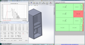
Yeah I modified post 24 to work in the larger 3d size, CreativeCaraudio has the driver, and lots of them, for 49.95 free shipping. I have a friend who wanted a PA sub and I was trying to make the most wood conservative design and thus pack space/weight light. I've made a few adjustments to the sim to account for the CAD measured volumes, if anyone is interested I can throw up the sldsm files. Attached are a refined image of the specs I'm using.
Yes you'll get build pics most likely and I have to do frequency response plots regardless (this cab is a prototype for a design I hope to replicate/refine). One question, what would happen if I had a removable piece on the back where there is an open space and removed the bottom section of the driver chamber?
The first two subs get the duratex treatment unless the prototype completely flops (not expecting it to). Future ones will get fancy stains and colors.
Question: what defines the conical connector lengths ? the box to the right of s2, s3, s4, s5 and by growing the box how much did they change? I have no idea how to convert the CAD for this into a number because I'm not sure what they are measuring.
Let me explain my reasoning behind using small strips (nominally the thickness of the material) running the joining side edges of the cab. at 12 inches wide per panel I don't have quite enough volume to get the tune/spacing right but 13 inches (or thereabouts) would not fit 4 panels to a 4x4, so I decided I would take a piece of alder, saw it up into strips the size i want and use those as "corner protector/panel joiners" with the side benefit of looking cool for when I eventually build a home theater version one of these and have different accents/stain for the different kinds of wood (eventually going to do a solid wood only variant).
I have no interest in response past 120 Hz and will be highpassing at 100 due to the Hornresp graphs but for educational purposes I'll definitely see what happens as I'm curious as to how accurate those insane spikes are as well.
Attachments
Last edited:
Sabaspeed ,
The fields next to "con" are centimeter lengths for the different segments of the pipe or horn, and normally they would help define most of the box with typical tapped horn , front loaded horn , tapped pipe etc boxes but since the majority of this box is actually made up of a giant throat chamber (defined by VTC and ATC) which means not only is this a little bit unorthodox but it also means that the S1 , S2 , S3 , S4 are just defining the very final section of the box (where the magnet of the woofer is) in other words the mouth of this box and it's associated chamber (section) ... The "con" after S4/S5 just sets the distance of the woofer's cone from the exit of the mouth...
"Con" (conical) can be clicked on to be made "par" (parallel panels) which is what we actually have when we build these boxes, but the difference between CON and PAR in the sim results are pretty insignificant.....Bass doesn't care.... Like most people I don't even bother with switching to PAR ...
I dont believe that the s1,s2,s3 etc will have to be increased by much in your scaled up model , only a little.. The sq cm should roughly match your "ATC" if it is a tapped pipe sort of configuration like this one is and your sim example is close enough ... and the amount of path length added by this section is effectively only several inches or so ...
To answer your question about moving the mouth/terminus to the bottom to make it end firing instead of side firing (or front firing), it is actually a great idea! , it extends the path length slightly which is good for you since you are trying to reach into the mid 30s") As you know it gives the box a different profile and a larger footprint, it would be a short & deep box arranged that way and if your friend is fine with that, then we have a winner ...
As you know it gives the box a different profile and a larger footprint, it would be a short & deep box arranged that way and if your friend is fine with that, then we have a winner ...
Also , before i forget to mention, about inductance (le) , i usually run my sims slightly high on the inductance value just to try to get a slightly more accurate sim.. It is something i learned from reading the forums here on DIYaudio ... A higher inductance tends to smooth out the underdamped peak at FB and more closely matches the real-world measurements that people are observing ... However i have to say that it is not likely a discrepancy in inductance that causes the smoothing that people see in real world measurements, but rather the small amount of losses that come from building a box out of wood instead of unobtanium or granite (as hornresponse simulates).
It is likely that your real-world measurements wont actually show the saddle & peak , but if it does you can add some poly , wool , or fiberglass stuffing/lining to the first 20% of the path (the area where the front of the cone fires into) in order to damp the peak and fill in the dip .......
The upper response peaks and dips in HR are also often overstated in simulation..
The fields next to "con" are centimeter lengths for the different segments of the pipe or horn, and normally they would help define most of the box with typical tapped horn , front loaded horn , tapped pipe etc boxes but since the majority of this box is actually made up of a giant throat chamber (defined by VTC and ATC) which means not only is this a little bit unorthodox but it also means that the S1 , S2 , S3 , S4 are just defining the very final section of the box (where the magnet of the woofer is) in other words the mouth of this box and it's associated chamber (section) ... The "con" after S4/S5 just sets the distance of the woofer's cone from the exit of the mouth...
"Con" (conical) can be clicked on to be made "par" (parallel panels) which is what we actually have when we build these boxes, but the difference between CON and PAR in the sim results are pretty insignificant.....Bass doesn't care.... Like most people I don't even bother with switching to PAR ...
I dont believe that the s1,s2,s3 etc will have to be increased by much in your scaled up model , only a little.. The sq cm should roughly match your "ATC" if it is a tapped pipe sort of configuration like this one is and your sim example is close enough ... and the amount of path length added by this section is effectively only several inches or so ...
To answer your question about moving the mouth/terminus to the bottom to make it end firing instead of side firing (or front firing), it is actually a great idea! , it extends the path length slightly which is good for you since you are trying to reach into the mid 30s
As you know it gives the box a different profile and a larger footprint, it would be a short & deep box arranged that way and if your friend is fine with that, then we have a winner ...Also , before i forget to mention, about inductance (le) , i usually run my sims slightly high on the inductance value just to try to get a slightly more accurate sim.. It is something i learned from reading the forums here on DIYaudio ... A higher inductance tends to smooth out the underdamped peak at FB and more closely matches the real-world measurements that people are observing ... However i have to say that it is not likely a discrepancy in inductance that causes the smoothing that people see in real world measurements, but rather the small amount of losses that come from building a box out of wood instead of unobtanium or granite (as hornresponse simulates).
It is likely that your real-world measurements wont actually show the saddle & peak , but if it does you can add some poly , wool , or fiberglass stuffing/lining to the first 20% of the path (the area where the front of the cone fires into) in order to damp the peak and fill in the dip .......
The upper response peaks and dips in HR are also often overstated in simulation..
Last edited:
Trying to figure this out
So you're saying that for this box the S1=S2=S3=S4=ATC due to the way the design works?
I'm still not quite getting how I would modify the CON fields other than the last one. So the one's that you nominally set to 0.1, 10, 10 and I have as .13, 11.5, 11.5, what do those correspond to?
I bumped up the inductance from 1.7 to 2.5 to accomodate for what you said.
Sabaspeed ,
The fields next to "con" are centimeter lengths for the different segments of the pipe or horn, and normally they would help define most of the box with typical tapped horn , front loaded horn , tapped pipe etc boxes but since the majority of this box is actually made up of a giant throat chamber (defined by VTC and ATC) which means not only is this a little bit unorthodox but it also means that the S1 , S2 , S3 , S4 are just defining the very final section of the box (where the magnet of the woofer is) in other words the mouth of this box and it's associated chamber (section) ... The "con" after S4/S5 just sets the distance of the woofer's cone from the exit of the mouth...
"Con" (conical) can be clicked on to be made "par" (parallel panels) which is what we actually have when we build these boxes, but the difference between CON and PAR in the sim results are pretty insignificant.....Bass doesn't care.... Like most people I don't even bother with switching to PAR ...
I dont believe that the s1,s2,s3 etc will have to be increased by much in your scaled up model , only a little.. The sq cm should roughly match your "ATC" if it is a tapped pipe sort of configuration like this one is and your sim example is close enough ... and the amount of path length added by this section is effectively only several inches or so ...
To answer your question about moving the mouth/terminus to the bottom to make it end firing instead of side firing (or front firing), it is actually a great idea! , it extends the path length slightly which is good for you since you are trying to reach into the mid 30s
Also , before i forget to mention, about inductance (le) , i usually run my sims slightly high on the inductance value just to try to get a slightly more accurate sim.. It is something i learned from reading the forums here on DIYaudio ... A higher inductance tends to smooth out the underdamped peak at FB and more closely matches the real-world measurements that people are observing ... However i have to say that it is not likely a discrepancy in inductance that causes the smoothing that people see in real world measurements, but rather the small amount of losses that come from building a box out of wood instead of unobtanium or granite (as hornresponse simulates).
It is likely that your real-world measurements wont actually show the saddle & peak , but if it does you can add some poly , wool , or fiberglass stuffing/lining to the first 20% of the path (the area where the front of the cone fires into) in order to damp the peak and fill in the dip .......
The upper response peaks and dips in HR are also often overstated in simulation..
So you're saying that for this box the S1=S2=S3=S4=ATC due to the way the design works?
I'm still not quite getting how I would modify the CON fields other than the last one. So the one's that you nominally set to 0.1, 10, 10 and I have as .13, 11.5, 11.5, what do those correspond to?
I bumped up the inductance from 1.7 to 2.5 to accomodate for what you said.
GM,
I played with CH mode a bit and found out that if you tune one resonant pipe or horn section to fill in the 3rd harmonic dip of the other you can actually get some decent output and wide-ish bandwidth ...
Greets!
Right, Olson’s production compound horn studio monitor had this feature as did his corner loaded studio monitor, which even by today’s standards had an impressive performance loaded with his 15” ‘full-range’ driver [attached] and of course DSL’s end loaded tapped ‘horns’ do the same thing in the same novel way originally done by Jensen.
GM
Attachments
Saba ,
You pretty much got it, the throat chamber (ATC & VTC) make up the majority of this box , while S1, S2 , S3 and so on only make up the last bit of the box where the woofer's magnet and the box's mouth are ... The length of centimeters on S2,S3 etc is only about the diameter of the woofer since the woofer just barely fits in there (or the distance between the exit of the constriction (port) to the outside world which i suppose is roughly 12 or 13" at best measured diagonally on the non end-fire version , but with your end-fire it is a little easier to estimate...Nevertheless its a rough estimation but the cm length of that section being slightly off isn't going to make any big difference really ...
and yes, about the access panel, since you are doing an end-fire version i guess you will need one unless you build the driver into the box permanently .... I suggest putting the access panel on the exit end of the pipe because pressures will be less there ...
Bracing would be moreso needed at the pressure end of the pipe (the closed end) and at the turn ... Arrange them parallel to the path like braces in tapped horns are arranged. Use thin material and be sure to put lots of big holes in them to reduce the amount of airspace taken up by the braces ...
You pretty much got it, the throat chamber (ATC & VTC) make up the majority of this box , while S1, S2 , S3 and so on only make up the last bit of the box where the woofer's magnet and the box's mouth are ... The length of centimeters on S2,S3 etc is only about the diameter of the woofer since the woofer just barely fits in there (or the distance between the exit of the constriction (port) to the outside world which i suppose is roughly 12 or 13" at best measured diagonally on the non end-fire version , but with your end-fire it is a little easier to estimate...Nevertheless its a rough estimation but the cm length of that section being slightly off isn't going to make any big difference really ...
and yes, about the access panel, since you are doing an end-fire version i guess you will need one unless you build the driver into the box permanently
.... I suggest putting the access panel on the exit end of the pipe because pressures will be less there ...Bracing would be moreso needed at the pressure end of the pipe (the closed end) and at the turn ... Arrange them parallel to the path like braces in tapped horns are arranged. Use thin material and be sure to put lots of big holes in them to reduce the amount of airspace taken up by the braces ...
GM, In fact speaking of compound designs, i think that if this ML-TP hybrid box shows an additional resonance up high due to the quasi-plenum then it would be a type of compound cabinet .... Three major resonances within the working range being the fundamental, 3rd harmonic, and quasi-plenum resonance ...
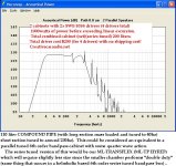
GM & Sabaspeed .... I decided to try to simulate this box in HR's "CH" (compound horn) mode ... 2 x SWE-10S4 per 100 liter cabinet ..... Interesting results IF the upper bandpass frequency is tuned to around 230hz it fills in the gap between the 3rd and 5th pipe harmonic and makes the response useable up to 300hz! (especially since the mass loading "constriction" of this cab shifts the frequency of the 3rd and 5th harmonic resonances somewhat higher than normal). This is great bandwidth for a 40hz tapped pipe!
Oh, and Sabaspeed, about the single driver cab, take a look at the sketch, im assuming this is what you were thinking about with the end-fire arrangement? A slightly scaled up version of what is in this sketch right?
Oh, and Sabaspeed, about the single driver cab, take a look at the sketch, im assuming this is what you were thinking about with the end-fire arrangement? A slightly scaled up version of what is in this sketch right?
Attachments
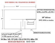
I'm actually will most likely end up doing side firing for the PA cabs and in a month or so when I build a HT version it will get the end firing variant, Access panels add like 2 hours of work lol. That's an interesting dual driver design, can you draw a skethup so i have a idea how that would look? Basically my design modifications are 31 inches total height 13.5 inches wide (12+ 2 thicknesses) 5.3-5.5 inches internal on the driver side 6 inches wide (internal) magnet side of baffle. Port is thus 6 inches long per section which measured center of path to center of path (each bend) is like 5ish.
GM & Sabaspeed .... I decided to try to simulate this box in HR's "CH" (compound horn) mode ... 2 x SWE-10S4 per 100 liter cabinet ..... Interesting results IF the upper bandpass frequency is tuned to around 230hz it fills in the gap between the 3rd and 5th pipe harmonic and makes the response useable up to 300hz! (especially since the mass loading "constriction" of this cab shifts the frequency of the 3rd and 5th harmonic resonances somewhat higher than normal). This is great bandwidth for a 40hz tapped pipe!
Oh, and Sabaspeed, about the single driver cab, take a look at the sketch, im assuming this is what you were thinking about with the end-fire arrangement? A slightly scaled up version of what is in this sketch right?
Response to 300 could make a very interesting tower design. Definitely interested to see if I can make it into the sub section of a skinny tower. Plenty of power for a home theater with dual 10's per cab.
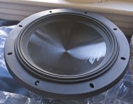
Drivers came early
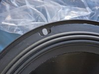
Bolts with pre installed nut inserts are a pain in my ***, because they aren't always easy to find at your local store (with the size you want, and they take a drill press and time to get them done right).
Driver in hand, wood cut. Probably starting assembly, trim cutting, and brace cutting on Friday.
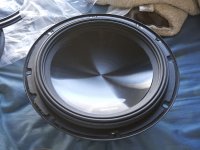
Creative Car Audio is awesome, order drivers Thursday, shipped Friday, Arrived across country (California) Tuesday. Did I mention it was UPS Freight and free? I'm sure glad shipping was free, these things are 13 pounds each. Quite high build quality for a Car audio 10 IMO.
Bolts with pre installed nut inserts are a pain in my ***, because they aren't always easy to find at your local store (with the size you want, and they take a drill press and time to get them done right).
Driver in hand, wood cut. Probably starting assembly, trim cutting, and brace cutting on Friday.
Creative Car Audio is awesome, order drivers Thursday, shipped Friday, Arrived across country (California) Tuesday. Did I mention it was UPS Freight and free? I'm sure glad shipping was free, these things are 13 pounds each. Quite high build quality for a Car audio 10 IMO.
Attachments

Saba ,
I am glad your order went so smoothly and that the delivery was prompt
Did you know that those drivers use santoprene surrounds? Neat stuff, and tough! Should be long lasting and impervious to the environment, much better than foam in these regards..
The Alpine SWE & SWS series are revered as being well built, well designed, durable and great performers, especially for the reasonable prices that they go for..... Its also nice that they have the specs that can be useful in higher efficiency alignments, not just the simple car audio boxes that most people use them in ... You can find lots of positive reviews for these drivers online ....
Since your boxes are tuned down to 35hz some of the SWS 10s might also be a good option for you if you needed even more XMAX and power handling but of course they are a little more expensive, still a great value though considering what they are capable of ......
You are right, if these turn out to be useful up to 300hz then maybe they could be made into some great 3 way towers as long as your mids can reach down to 300hz ..
The dual driver compound pipe box i simmed using HR's "CH" mode is just something that i wanted to use to try to get an better idea of what the response of our hybrid box might really be (including the 3rd resonance, that potential quasi-plenum resonance that HR doesn't include in TH mode ) ... So i was basically just trying to create an equivalent in a different mode as an experiment IN THE NAME OF SCIENCE!!.... However, as a compound pipe it is a very simple build, and is only slightly larger than the ML-transflex hybrid cabinet and appears to be well damped (less of the "saddle" response curve) ... It also can be easily scaled down to fit one driver and ends up being almost the same size as the hybrid..... I will post sketches of both for you so you can see whats inside the box and compare, they are extremely similar really....
I am glad your order went so smoothly and that the delivery was prompt
Did you know that those drivers use santoprene surrounds? Neat stuff, and tough! Should be long lasting and impervious to the environment, much better than foam in these regards..
The Alpine SWE & SWS series are revered as being well built, well designed, durable and great performers, especially for the reasonable prices that they go for..... Its also nice that they have the specs that can be useful in higher efficiency alignments, not just the simple car audio boxes that most people use them in ... You can find lots of positive reviews for these drivers online ....
Since your boxes are tuned down to 35hz some of the SWS 10s might also be a good option for you if you needed even more XMAX and power handling but of course they are a little more expensive, still a great value though considering what they are capable of ......
You are right, if these turn out to be useful up to 300hz then maybe they could be made into some great 3 way towers as long as your mids can reach down to 300hz ..
The dual driver compound pipe box i simmed using HR's "CH" mode is just something that i wanted to use to try to get an better idea of what the response of our hybrid box might really be (including the 3rd resonance, that potential quasi-plenum resonance that HR doesn't include in TH mode ) ... So i was basically just trying to create an equivalent in a different mode as an experiment IN THE NAME OF SCIENCE!!
.... However, as a compound pipe it is a very simple build, and is only slightly larger than the ML-transflex hybrid cabinet and appears to be well damped (less of the "saddle" response curve) ... It also can be easily scaled down to fit one driver and ends up being almost the same size as the hybrid..... I will post sketches of both for you so you can see whats inside the box and compare, they are extremely similar really....Thanks for the SWS 10s mention, I just wrote a very long post about how awesome a set of 4 in a club for 2k (what I charge them) would be. Mind blowing concert bass. So stoked to make that happen.
Just met someone last night who can make the introduction and demo happen, just need to make some stockpile cabs now.
Just met someone last night who can make the introduction and demo happen, just need to make some stockpile cabs now.
Excellent! Thank you for that Saba , the specs aren't too far off from what is published ....
So those figures give us:
FS:42
QES=.69
QMS=6.84
VAS=21.14
QTS=.62
As the driver breaks in the QES/QTS will drop a little as VAS increases slightly ... FS will likely drop down to around 40hz over time ...
So those figures give us:
FS:42
QES=.69
QMS=6.84
VAS=21.14
QTS=.62
As the driver breaks in the QES/QTS will drop a little as VAS increases slightly ... FS will likely drop down to around 40hz over time ...
Using these in a club would work if you had enough boxes to pressurize the space properly ... You could even use the Geddes approach and arrange the cabs in different parts of the room to even out the response throughout the space and have more consistent bass no matter where a person is standing , but that would likely require some experimentation with placement ..
I imagine that these cabinets would not have the uber punchy midbass sound (apparent loudness) that people normally associate with PA bass cabinets, but a moreso hi-fi sound with a nice full bottom end ..
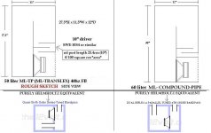
I made another sketch for you showing the differences between what i have simulated , you can see we are basically making equivalents to bandpass cabinets but working in some quarter wave action to benefit from the higher efficiency and increased bandwidth of using this type of loading... The plenum/bandpass (smaller chamber) resonant frequency is easier to predict with the parallel (compound pipe) version. ... These are 40hz versions just for example but of course you would want to scale up if needing a 35hz FB, however some of these sims show that even with the 40hz tuned cabs 35hz is only 3db down (excursion is exceeded below that at full power though) ...
For the sake of this comparison I made them similar in size with the larger cab being only slightly taller but I think that the compound version made even taller (longer path) simmed a little better with flatter response up into the midbass , however this makes the cab less deep so the plenum (small bandpass chamber) will be tuned too high to be effective, so some mass loading like what you saw in the compound scoop pictures i posted earlier would be required to bring that resonance back into the proper range .. Its easy enough to achieve, you just add a plate mounted in front of the small chamber with a constriction .. Easy to sim too ..
By the way Saba , have you seen the special run of LAB15 drivers that people have been talking about here on DIYaudio? They are very affordable and look like they might have the specs that would work well in some larger 35hz hybrid cabs, not as portable but perfect for permanent install situations ..... I will have to sim some of those special Labs to see how they look ...
Anyhow , I still don't know what to call these things but if your prototype works well enough to make you happy i suppose we will have to come up with something catchy
I imagine that these cabinets would not have the uber punchy midbass sound (apparent loudness) that people normally associate with PA bass cabinets, but a moreso hi-fi sound with a nice full bottom end ..
I made another sketch for you showing the differences between what i have simulated , you can see we are basically making equivalents to bandpass cabinets but working in some quarter wave action to benefit from the higher efficiency and increased bandwidth of using this type of loading... The plenum/bandpass (smaller chamber) resonant frequency is easier to predict with the parallel (compound pipe) version. ... These are 40hz versions just for example but of course you would want to scale up if needing a 35hz FB, however some of these sims show that even with the 40hz tuned cabs 35hz is only 3db down (excursion is exceeded below that at full power though) ...
For the sake of this comparison I made them similar in size with the larger cab being only slightly taller but I think that the compound version made even taller (longer path) simmed a little better with flatter response up into the midbass , however this makes the cab less deep so the plenum (small bandpass chamber) will be tuned too high to be effective, so some mass loading like what you saw in the compound scoop pictures i posted earlier would be required to bring that resonance back into the proper range .. Its easy enough to achieve, you just add a plate mounted in front of the small chamber with a constriction .. Easy to sim too ..
By the way Saba , have you seen the special run of LAB15 drivers that people have been talking about here on DIYaudio? They are very affordable and look like they might have the specs that would work well in some larger 35hz hybrid cabs, not as portable but perfect for permanent install situations ..... I will have to sim some of those special Labs to see how they look ...
Anyhow , I still don't know what to call these things but if your prototype works well enough to make you happy i suppose we will have to come up with something catchy
Attachments

Last edited:
- Status
- This old topic is closed. If you want to reopen this topic, contact a moderator using the "Report Post" button.
- Home
- Loudspeakers
- Subwoofers
- New sub design? Constricted Transflex, simple build (series tuned 6th order)