Hello
After recently building some sealed subwoofers I would like to determine the F and Q of the system to create a dsp Linkwitz Transform.
Are there any free measurement apps that will give exact figures of the final subwoofers Q and F? I did simulate the build in winisd first but the cones of the woofers had some mass added to them (plasti dip rubber coating) and the box size ended being a bit different (braces).
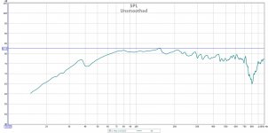
Can you tell from the graphs accurate F and Q values?
The measurement was taken 1.5 inches from one of the drivers dust caps - that's another thing I am not sure of for a subwoofer with 2 drivers is the dust cap of one the correct place for nearfield measurement or should it be the point on the baffle between the 2 drivers?
Also from the graphs would you say I have too much fill or not enough?
After recently building some sealed subwoofers I would like to determine the F and Q of the system to create a dsp Linkwitz Transform.
Are there any free measurement apps that will give exact figures of the final subwoofers Q and F? I did simulate the build in winisd first but the cones of the woofers had some mass added to them (plasti dip rubber coating) and the box size ended being a bit different (braces).
Can you tell from the graphs accurate F and Q values?
The measurement was taken 1.5 inches from one of the drivers dust caps - that's another thing I am not sure of for a subwoofer with 2 drivers is the dust cap of one the correct place for nearfield measurement or should it be the point on the baffle between the 2 drivers?
Also from the graphs would you say I have too much fill or not enough?
Attachments
Last edited:
Hello
After recently building some sealed subwoofers I would like to determine the F and Q of the system to create a dsp Linkwitz Transform.
Are there any free measurement apps that will give exact figures of the final subwoofers Q and F? I did simulate the build in winisd first but the cones of the woofers had some mass added to them (plasti dip rubber coating) and the box size ended being a bit different (braces).
Can you tell from the graphs accurate F and Q values?
The measurement was taken 1.5 inches from one of the drivers dust caps - that's another thing I am not sure of for a subwoofer with 2 drivers is the dust cap of one the correct place for nearfield measurement or should it be the point on the baffle between the 2 drivers?
Also from the graphs would you say I have too much fill or not enough?
Hi charliecola,
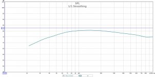
Measure the SPL = SPL1 close to the Cone(~1 cm) at the Box resonance frequency(f(0)) and at a sufficiently higher frequency where the FR begins to flatten out= SPL2, i.e. where the Driver Cone is Mass-controlled.
For your case this ocuurs at ~100-190 Hz using the smoothed FR Curve. The Box System Q is then simply;
Q(0)= 10^(SPL1-SPL2)/20...
.. at the specific frequency = f(0).Enter Q(0) and f(0) into a LT Spreadsheet, specify f(p) and Q(p) to target a new BW.
b
")
If you take an impedance curve, it would be much easier to determine Fb and Q. However, in the absence of that, BJorno's suggestion should work.
If that raw response curve is a close-miked one, it suggests that you might have a leak in the box (this could be the cause of the "blip" at the low frequency side of the raw response).
If that raw response curve is a close-miked one, it suggests that you might have a leak in the box (this could be the cause of the "blip" at the low frequency side of the raw response).
Hello
Thank you all for your helpful replies.
Bjorno your method helped me to understand the measurement but I was wondering about a single accurate measurement.
I think you were right Mr Steele about the leak - I installed Neutrik Speakon connectors as they are supposed to be gas tight. On the second subwoofer I added more sealant and the dip at 40 was much less but clearly still leaking from the same place.
I done an impedance measurement with REW. Is the Fb simply the peak of the curve i.e 44hz? How do I determine Q from this curve?
Best Regards
Attachments
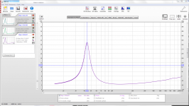
I done an impedance measurement with REW. Is the Fb simply the peak of the curve i.e 44hz? How do I determine Q from this curve?
Do you have a copy of the Loudspeaker Cookbook by Vance Dickason? The process described therein to measure a driver's Q can also be used to determine Qb. It takes longer to explain it than to do it
.Here's the abbreviated version - Bjorno can check my math and process here:
1. Obtain Re, the driver's DC resistance
2. Obtain Rm, the impedance at Fb, the peak of the impedance curve
3. Calculate r0 = Rm/Re
4. Calculate Rz = (Re*Rm)^0.5
5. Obtain F1 and F2, where R=Rz on the impedance curve
6. Confirm Fb = (F1*F2)^0.5
7. Calculate Qmb = Fb*R0/(F2-F1)
8. Calculate Qeb = Qmb/(r0-1)
9. Calculate Qtc = Qeb*Qmb/(Qeb+Qmb)
Aside from theoretical interest, why would you want to get into the Linkwitz Transform when you have the acoustical output results?
You have your empirical result. Want to make sure your theory computes or want to tweak the particular sound in your room?
Do your two curves match to a satisfactory degree and/or better than any other sealed box with any more or less simillar drivers?
BTW, in practical practice you don't want a perfectly sealed box unless you live in a perfectly controlled atmosphere room.
Ben
Last edited:
Hello
Thank you all for your helpful replies.
Bjorno your method helped me to understand the measurement but I was wondering about a single accurate measurement.
I think you were right Mr Steele about the leak - I installed Neutrik Speakon connectors as they are supposed to be gas tight. On the second subwoofer I added more sealant and the dip at 40 was much less but clearly still leaking from the same place.
I done an impedance measurement with REW. Is the Fb simply the peak of the curve i.e 44hz? How do I determine Q from this curve?
Best Regards
If you did the impedance measurement in REW, go to Thiele Small parameters and add some (known) mass to the driver cone and repeat measurement - REW can calculate the Qes, Qms, Qts for you as if it were a bare driver - but now the Q is with the effect of the box. I think that should work (only for sealed alignment as it has one peak only).
Hello
I am just looking for the F and Q of the box to put into this spreadsheet: Linkwitz Transform | MiniDSP
Hi Ben, I don't have much of a theoretical interest, just want to apply appropriate LT to the subs. I am happy with the curves.
Instead of Linkwitz Transform can as good a result be achieved by setting everything up then eqing to final desired result with low shelf/peq?
From what I've read people tend to apply LT first based on close mic measurements then additional eq from listening position. I would be happier actually to simply eq the sub into the room from it's raw response and have less eq going on overall - perhaps once it is in the room the room gain may remove necessity for LT?
I am just looking for the F and Q of the box to put into this spreadsheet: Linkwitz Transform | MiniDSP
Aside from theoretical interest, why would you want to get into the Linkwitz Transform when you have the acoustical output results?
You have your empirical result. Want to make sure your theory computes or want to tweak the particular sound in your room?
Do your two curves match to a satisfactory degree and/or better than any other sealed box with any more or less simillar drivers?
BTW, in practical practice you don't want a perfectly sealed box unless you live in a perfectly controlled atmosphere room.
Hi Ben, I don't have much of a theoretical interest, just want to apply appropriate LT to the subs. I am happy with the curves.
Instead of Linkwitz Transform can as good a result be achieved by setting everything up then eqing to final desired result with low shelf/peq?
From what I've read people tend to apply LT first based on close mic measurements then additional eq from listening position. I would be happier actually to simply eq the sub into the room from it's raw response and have less eq going on overall - perhaps once it is in the room the room gain may remove necessity for LT?
LT, as I poorly understand it, is a kind of second-order fillip on a model to produce a simulation which achieves flat output whereas the basic T-S model beloved here seeks to define output based on constant voltage input.
But your situation is different because you have an empirical result, not number-play. In addition, as seems to be constantly forgotten, the aim is to achieve a preferred house-curve, not flat output. Getting a fabulous low frequency output can often bring along problems which, funny thing, aren't part of the T-S model world such as floppy cones and Doppler distortion.
Sticking with the reality of what you have built, wouldn't it be better to simply equalize the curve at ear-level to your satisfaction instead of doing number-play with LT for some abstract purpose that seems academic?
Ben
Last edited:
Ben,
When designing a Linkwitz Transform, it's still preferable to have an actual acoustic measurement vice basing everything on an impedance measurement. The objective is not only to extend flat output but also to achieve a desired Q of the resultant roll-off.
The original op-amp hardware implementation of the Linkwitz Transform is somewhat outdated now since DSP boxes can easily create whatever curve is required, but it's still not a wasted effort to understand the theory of the second-order roll-off and how to EQ it.
Your point is still perfectly valid though. He has an actual (very close) acoustic measurement that can be used for either calculation/simulation OR simply just applying EQ empirically with a DSP box to achieve whatever the desired result. No reason you can't perform just the latter.
Cheers,
Dave.
Dave -Ben,
When designing a Linkwitz Transform, it's still preferable to have an actual acoustic measurement vice basing everything on an impedance measurement. The objective is not only to extend flat output but also to achieve a desired Q of the resultant roll-off.
The original op-amp hardware implementation of the Linkwitz Transform is somewhat outdated now since DSP boxes can easily create whatever curve is required, but it's still not a wasted effort to understand the theory of the second-order roll-off and how to EQ it.
Your point is still perfectly valid though. He has an actual (very close) acoustic measurement that can be used for either calculation/simulation OR simply just applying EQ empirically with a DSP box to achieve whatever the desired result. No reason you can't perform just the latter.
Cheers,
Dave.
A very clear and information-filled reply. Thanks. And although I am not well-informed:
Yes, toss out that theoretical T-S stuff premised pre-construction and then use the no-doubt different measured values to reverse engineer the driver-box system.
I think what you are saying is that with the possibility of measuring the box performance, you can "deconstruct" the system back into its driver-in-the-box T-S elements simulation. Then, with your values in hand and with the LT model, you can do your tweaking.
Or you can just do your EQ tweaking and get on with it, as I think you are suggesting at the end.
Moreover, achieving the ear-happy sound may not be the same of some electrical engineering textbook notion of the Q that would be generally used for electrical things. What Q is right, psycho-acoustically speaking? Is there a theoretically correct Q for your vehicle's suspension?
Ben
- Status
- This old topic is closed. If you want to reopen this topic, contact a moderator using the "Report Post" button.
- Home
- Loudspeakers
- Subwoofers
- Determine F and Q through with Room EQ Wizard