Hi,
yes it´s +-100g, which is more than one needs apart maybe freom some few ultra longstroke woofers doing maximum excursion @50Hz.
+-50g is more realistic I think.
Similar to an AD-Converter dynamic range was - and maybe still is- a major concern for the MEMs.
So You want one that offers just a slightly greater g-range than what is required maximally and You want the lowest noise figure for best resolution.
The ADXL1002 has a noise figure of 1/3 of the ADXL1005.
Also its sensitivity is roughly twice as high ... should improve signal handling at lower volume levels and keeping the acceleration signal out of the noise floor.
The +-100g ADXL1001 is also lower in noise figure.
jauu
Calvin
Just curious, what woofers and how much power do you generally use for your MFB designs?… +-100g, which is more than one needs apart maybe freom some few ultra longstroke woofers doing maximum excursion @50Hz.
+-50g is more realistic I think.
The reason I ask is that I easily exceeded 100G peaks with Peerless 10” and 12” woofers driven with 300W BASH plate amps using the ACH-01 sensor. Is it possible you are thinking of RMS rather than Peak acceleration?
I know I had posted these figures before somewhere so apologize for the repeat, but can’t seem to locate them.
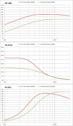
The first compares SPL, excursion, and acceleration for a 15” woofer driven with 1500W and a 10” woofer driven with 200W.
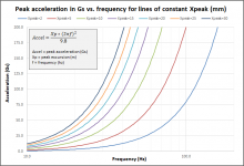
As you mentioned, it is not at the lowest frequencies that you run into high Gs, but at the upper range of the subwoofer. This is because peak acceleration is proportional to peak excursion times the square of the frequency. The second attachment provides some acceleration trends lines for a range of peak excursions. For the 50Hz example you mention, with peak excursion of only 5mm you would already be bumping the 50G limit.
BTW, there is also an ADXL1003 currently available at Mouser which is +/-200G with 45µg/sqrt(hz) noise.
https://www.analog.com/media/en/technical-documentation/data-sheets/ADXL1003.pdf
https://www.mouser.com/datasheet/2/609/ADXL1003-1503766.pdf
Attachments
Last edited:
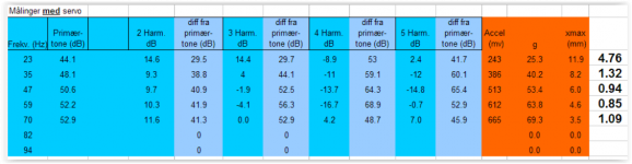
Attaced is measurements I did on a Peerless XLS 10" with 30V RMS (225W) at various frequencies.
At 47Hz I passed 50g and at 70Hz I had 69g. Above that I ran into problems with the coil rubbing into the magnet because I mounted the sensor on one side of the voice coil without any counter weight on the opposite side. The remaining THD is on the left of the table. 1,32% is down from 8,4% with the same signal without servo.
So 100g is absolutely something that can be neccesary. But I totally agree that if the design goal is less than 50g the ADXL1002 is a better choice.
The ADXL1001 seems to be the best option for 100g applications. It has better linearity with 0,1% vs 0,25% for the ADXL1005. The noise is also slightly better. But not that much smaller than the ADXL1005. The number is given with two different bandwiths in the two datasheets. 10kHz vs 20kHz for the ADXL1005.
It seems the old ACH-01 is still the noise king, but I am unsure how much noise affekts the system. The maximum linearity error of the ACH-01 is also 1% and its low frequency stability is not as good. I remember having oscillations around 1Hz. I guess we just have to try and see.")
At 47Hz I passed 50g and at 70Hz I had 69g. Above that I ran into problems with the coil rubbing into the magnet because I mounted the sensor on one side of the voice coil without any counter weight on the opposite side. The remaining THD is on the left of the table. 1,32% is down from 8,4% with the same signal without servo.
So 100g is absolutely something that can be neccesary. But I totally agree that if the design goal is less than 50g the ADXL1002 is a better choice.
The ADXL1001 seems to be the best option for 100g applications. It has better linearity with 0,1% vs 0,25% for the ADXL1005. The noise is also slightly better. But not that much smaller than the ADXL1005. The number is given with two different bandwiths in the two datasheets. 10kHz vs 20kHz for the ADXL1005.
It seems the old ACH-01 is still the noise king, but I am unsure how much noise affekts the system. The maximum linearity error of the ACH-01 is also 1% and its low frequency stability is not as good. I remember having oscillations around 1Hz. I guess we just have to try and see.
Attachments
...BTW, there is also an ADXL1003 currently available at Mouser which is +/-200G with 45µg/sqrt(hz) noise.
https://www.analog.com/media/en/technical-documentation/data-sheets/ADXL1003.pdf
The spec for that ADXL1003 says, "Linearity to ±0.2% of full-scale range". But if the full range is 400 G's, does that make the extent of linearity poor for small signals? With feedback, what's in the loop is the whole story; so noise and distortion introduced by the sensor have to be a whole lot better than the previously non-looped system the sensor is meant to fix.
Also, seems to have an 8-lead cable. I wonder if that is kind of heavy to work with a driver?
I wonder how the ACH-01 or the new accelerometers actually perform with increasing cone motion and what the failure mode sounds like?
Thanks.
B.
Last edited:
There certainly is much ambiguity in the linearity specification. The datasheet states that the testing was performed using 13kHz sine vibration, but does not indicate what G level was used. Ideally we would have a %THD vs G curve. Hands on testing or additional information from the manufacturer would be needed.
Linearity of mechanical sensors that I deal in my day job are always much better for small signals(sometimes an order of magnitude better) and gets poorer as you approach the specification extremes. I would anticipate the MEMS devices to behave similarly, but can’t say for sure.
The MEMS device weighs a mere 0.2g, compared to 3.5g for the ACH-01.
Only 3 wires would be needed for MFB use so weight should not be a concern.
The MEMS device has sensitivity scaled to a ratio of the supply voltage. Output will clip once the peak output range is exceeded. According to the datasheet the device is also toggled on/off in 500uS intervals until the G level falls back in range. That wouldn’t sound pretty.
Thanks for sharing your measurements…a nice match with simulation from the values I calculated assuming free-air operation of the XLS10. Those are RMS values so the 69g would require 98g peak capability from the sensor, correct?Attaced is measurements I did on a Peerless XLS 10" with 30V RMS (225W) at various frequencies. At 47Hz I passed 50g and at 70Hz I had 69g.
Hi,
@bolserst
I can´t give a A to Q#223 about which woofer I use.
I´d like to use some of the TCsounds, but then TSound seems to have gone off market again.
There are too numerous longthrow sub drivers around to just fixate on a single one.
Overload behaviour certainly is one of the major concerns in a fedback system.
500µs togle intervall translates to 2kHz which should be easy to filter out and smooth with a lowpass.
And certainly the overload conditions won´t last for long ... it may repeat after a few tens ms but the overload condition itself may last alot shorter.
jauu
Calvin
Thanks for sharing your measurements…a nice match with simulation from the values I calculated assuming free-air operation of the XLS10. Those are RMS values so the 69g would require 98g peak capability from the sensor, correct?
It is 10 years since I did those measurements, but if I recall correctly the g's in the table are peak.
I hope I can find time in the coming year to test the new ADXL sensors and will of course post my findings here.
I have used ordinary piezo tweeter chrystals with success.
Make sure to put an OP amp buffer close to the sensor since the piezo chrystal has high output impedance.
I am concerned about the linearity of cheap piezo sensors. Do you have any data or measurements?
Hi,
for some reason this thread seems to be hooked to high tech acceleration sensors. Maybe if we could have a look at other sensors too, from the other side, there might be simpler alternatives even better suited? Instead of asking for real data as a sensor in a woofer, a look as how something performs as a transducer could give some hint. So the distortion of a piezo tweeter will be somehow similar to its sensor abilities and they do quite good. Also there are simple coils with diaphragms, moved in a magnetic field, which form microphones with remarkable low distortion. My last idea are two opposite areas that form a capacitor and can be integrated easily in a large woofer with decent voice coil.
Is there a point I have missed that makes these analog devices unfit for the task?
In my opinion nothing would be more convenient, also seen under a DIYS perspective, than a separate, small coil under the dust cap, with a tiny magnet in it, giving a perfect signal for a correction circuitry. A piezo extracted from a tweeter, with added mass should be worth a try, too.
Hunting for lowest distortion might not be the ultimate aim, there is some tolerance for it under 200 Hz if we could use this as the upper limit for a “true woofer”. As well, reduced distortion will always be a side effect of any MFB.
In the past, the need for stable high power amplifier was the most important cost factor of MFB, making it unattractive for commerce.
A long time ago I build some simple active loudspeakers with a resistor in the negative wire. The closed cabinet was 120 liters and extremely well build, the speakers cheap 12” with relatively small magnets, about .7 Qts and 25 Hz resonance, but (for that time) long travel, +-6mm linear. Crossover was 100 Hz 12db/cot The audible result was incredible impressing, deep and dry. The speakers had an 4 Ohms 100 watts rms rating, but the amps, each with a 600W torodial, could be seen short before clipping on the oscilloscope at +- 60 volts. At this power level the sound was still distortion free. So two 400 watt amps where needed for party level sound pressure, at least twice the energy for the plain speaker. Although the membrane was moving in and out like crazy, the woofer had no problems. At that time such strong amps where heavy and prohibitive expensive, not to speak of the second pair, needed for the conventional mid-high two way speakers.
After some problems where solved, the adjusted system was surprisingly stable and worked for a few years, until the woofers foam surrounds fell apart. To achieve final stability I had to use thick wires, ground the loudspeaker chassis and place the amp close behind the speaker. The resistor for feed back and potentiometer for adjusting it where directly behind the speaker terminal, cutting wires to under one meter. Until the amps reached temperature, the speaker cone moved about 1 mm out, but this did not effect the function.
I experimented with a Philips MFB woofer, too, but the sensor was always running away and had to be constantly readjusted. Maybe the amp was not stable enough. Anyway, I did not see much use in a small 7” or so, tortured to give 30Hz or even deeper at low volume.
From my perspective, the Phillips stuff was not the final system, just cheep stuff over developed and much too expensive. Makes more sense making a good woofer better than turning a cheap, mediocre loudspeaker in a good one, like Phillips did.
The Philips speakers did not excel, if size was no factor. They sounded good, but not better than average., no winner at all. There where many passive speakers at that time, sounding much more fascinating.
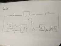
motional feedback block schematic
Hello everybody,
I hope you don't mind if I reissue an old thread.
I have been thinking about the implementation of the motional feedback, and i didn't completely understand the circuit shown in the 1st page
when i don't understand something after many tries, usually I try to rebuild it from scratch, and so i did.
I designed a schematic and I simulated it with LTspice, and here i propose you a block schematic of what i simulated: it seems to work.
Is it the same thing of the schematic shown in page 1 but made a different way? do you think my schematic makes sense?
Here is a legenda:
U is a voltage difference amplifier circuit (the typical one with an opamp)
S is the signal source
A is the power amplifier
K the speaker
F is the accelerometer + its gain stage.
a is the musical signal,
b is the distortion that the speaker tries to introduce
a and b are visual supports i used to visualize the concept: In my LTspice simulation basically i introduced a series high frequency sinusoidal voltage source instead of the blocks A, K and F
do you think this makes sense or did i miss something?
Cheers,
Sergio
Attachments
Nice thinking, though note that A, K and F have a frequency dependent transfer function and can exhibit nonzero phase. Then both reasons cause the subtraction in (upper) U to become incorrect.
MFB typically uses the tried-and-true negative feedback schema with an open loop gain that peaks to 20..30 dB.
MFB typically uses the tried-and-true negative feedback schema with an open loop gain that peaks to 20..30 dB.
Thank you for your input TBTL,
actually i didn't introduce a sub-like phase-dependent transfer function for K in my simulation, but now, thanks to your suggestion, I added it in the last model.
Anyways, do you specifically refer to stability issues?
Can you please share a block schematic or explain me another way the 30 dB open loop gain thing?
In my second-last model, I used an active low-pass and an active high-pass filter at the output of the accelerometer, and when there, i added the phase shift of the speaker, i had the sistem to oscillate.
without the low pass filter, it's stable again.
Thank you,
Cheers
S.
For now, just in my dreams Boden
i am just doing some circuit design for now. If you are interested, I just found two bachelor degree theses that contain lots of useful info:
https://repository.tudelft.nl/islandora/object/uuid:8aa8e841-24f1-458a-bebd-bae82033bb7b/datastream/OBJ/download
Motional Feedback in a Bass Loudspeaker | TU Delft Repositories
In general it looks like in the university of Delft they really like this topic!
Especially interesting, the use of an integrator for correcting the phase on the lower end of the frequency spectrum.
Cheers,
S.
- Status
- This old topic is closed. If you want to reopen this topic, contact a moderator using the "Report Post" button.
- Home
- Loudspeakers
- Subwoofers
- Analog Servo Sub