That is exactly the concept. The remote sensing wires in the SIGMA configuration ensure that the voltage waveform at the binding posts of the speaker matches the voltage waveform at the input of the amplifier. It does not account for woofer motion, or even if there is a woofer connected at all....yes, the Sigma circuit kind of looks like the hook-up for remote-sensing of a bench power supply delivery.
Since you are fond of mentioning how a MFB woofer cone feels “stiff” when you push against it, give it a try next time you have access to a SIGMA wired amplifier. You will find the woofer cone feels no different than if you were to short the VC of the woofer with a wire.
There isn’t a disconnect between those two statements if you don’t take them out of context.Whatever the non-linearities are, they just can't be much or the sound would be awful. You can't have it both ways: (a) my speaker sounds good and (b) your VC MF works terrible.
What is being said is that no matter how good your woofer motor, if you use it as a sensor for MFB you will never be able to reduce distortion below the level of the motor distortion. That is all.
Where VC feedback is most useful is below resonance at moderate excursions where motion is stiffness controlled and motor linearity is still good. In this situation a decent woofer has a motor that is linear enough to reduce stiffness related distortion with VC feedback by a factor of 3 or so until you start exceeding about 50% of Xmax and motor linearity deteriorates.
The fact remains that to reduce distortion by large factors (or distortion to levels <1% ) over the whole woofer operating range(frequency and excursion) you need to use an accelerometer or a separate VC/magnet structure specificlly designed for linearity over the full woofer operating range.
That is exactly the concept. The remote sensing wires in the SIGMA configuration ensure that the voltage waveform at the binding posts of the speaker matches the voltage waveform at the input of the amplifier. It does not account for woofer motion, or even if there is a woofer connected at all.
Since you are fond of mentioning how a MFB woofer cone feels “stiff” when you push against it, give it a try next time you have access to a SIGMA wired amplifier. You will find the woofer cone feels no different than if you were to short the VC of the woofer with a wire.
Right. I think you are almost admitting the Sigma Drive really is similar an MFB circuit... but the resistance values of the wires are too small to have too much effect. You can also think of the Sigma Drive as a colossally low output impedance.
There isn’t a disconnect between those two statements if you don’t take them out of context.
What is being said is that no matter how good your woofer motor, if you use it as a sensor for MFB you will never be able to reduce distortion below the level of the motor distortion. That is all.
Where VC feedback is most useful is below resonance at moderate excursions where motion is stiffness controlled and motor linearity is still good. In this situation a decent woofer has a motor that is linear enough to reduce stiffness related distortion with VC feedback by a factor of 3 or so until you start exceeding about 50% of Xmax and motor linearity deteriorates.
The fact remains that to reduce distortion by large factors (or distortion to levels <1% ) over the whole woofer operating range(frequency and excursion) you need to use an accelerometer or a separate VC/magnet structure specificlly designed for linearity over the full woofer operating range.
This matter of imperfect motors can't be considered without thinking about the purposes of MF as bolserst and I have been saying. For over- and under-shoots, modest irregularities don't matter. Nor to take bolserst "most useful" instance, these irregularities mean nothing in terms of making the cone do your bidding right at system resonance and, miraculous to say, below system resonance too.
With all the human effort that's gone into cabinet tricks for addressing resonance and below, MF seems a pretty smart way to go. And esp. since many DIYaudio members can explore this whole matter which needs zero additional bits and pieces (from what most of us have sitting around on our workbenches) in just a few minutes of set-up time.
Ben
Last edited:
No sir, quite the opposite. The only similarity is that feedback is involved.Right. I think you are almost admitting the Sigma Drive really is similar an MFB circuit... but the resistance values of the wires are too small to have too much effect.
MFB uses feedback to make the woofer cone motion(velocity or acceleration depending on sensor type) more closely match the input voltage waveform.
SIGMA uses feedback to make the signal voltage applied to the woofer more closely match the input voltage waveform.
How well the woofer cone motion follows this applied signal voltage has no bearing whatsoever on the signal sent back thru the feedback loop in the SIGMA circuit.
So, no MFB is involved no matter what resistance values the wires have.
I don't know how better to describe the difference.
Had to read that a few times.
With effective resistance in the feed to the driver, the Sigma Drive compares the motion of the cone (as revealed by the way the back EMF changes the driver impedance) with the input.
(If I were better educated, I'd know how to describe it in terms of negative output impedance and current sources.)
Call it what you want, but sure sounds like motional feedback to me.
In practice, you wouldn't just treat the Kenwood Basic amp like a "black box" and play games with the Sigma Drive wires. All I am saying is that there is really little difference in principle between remote sensing, Sigma Drive, and motional feedback. Unless like bolserst, you don't want to relate VC behaviour to cone behaviour. Or should I read that one more time?
Ben
Last edited:
This is not true. The Sigma circuit does not compare cone motion with input voltage.With effective resistance in the feed to the driver, the Sigma Drive compares the motion of the cone (as revealed by the way the back EMF changes the driver impedance) with the input.
The driver does generate back EMF in both cases, but what a MFB bridge circuit does with it is completely different than what the Sigma circuit does.
In principal, a MFB bridge circuit isolates the back EMF voltage from the amplifier output voltage applied to the VC and compares it with the input voltage. The feedback circuit operates to keep the back EMF voltage as close a replica of the amplifier input as possible. The back EMF is directly proportional to cone velocity, so it is doing its best to control cone motion.
The Sigma remote sensing wires compare the voltage applied to the VC(amplifier output voltage minus any voltage drops along the wires) with the input voltage. The feedback circuit operates to counteract the voltage drops from wire resistance and fluctuating load impedance(back EMF) to keep the voltage applied to the VC as close a replica of the amplifier input as possible. Rather than controlling cone motion, it is doing its best to ignore it.
Perhaps forgetting all the details and looking at it from a control perspective will make the distinction clearer:
MFB is designed to control motion of the woofer cone.
It has the potential ability to reduce inherent woofer motor/suspension nonlinearities,
flatten the woofer system response, and improve transient response.
Sigma Drive is designed to control the voltage applied to the VC.
The best it can hope to achieve it to match the performance of the woofer system driven by a perfect voltage source.
The acoustic output of the woofer system will include all its inherent motor/suspension nonlinearities and natural LF roll off behavior.
So… no distortion reduction, no response flattening, and no transient response improvement.
In short, none of the positive attributes of MFB.
MF specific drivers
Someone mentioned earlier that MF-specific drivers should be developed. I think that this is what Genesis did. I owned the Genisis 900 subwoofer which used an accelerometer (it was the predecessor to the Genesis 928). The driver for this subwoofer is aluminum - a very stiff cone, which provided a good surface for mounting the accelerometer. It is interesting that Genesis employed stamped frame drivers - they probably figured that the motion feedback would "fix" the nonlinerarities and resonaces of the stamped frame - or more likely, perhaps, they just wanted to save costs.
I recall when I first got this subwoofer, that it played OK, but was nothing special. I called up Genesis at one point to ask them about something, and the guy I spoke to mentioned that they developed a better method to afix the accelerometer to the driver which further lowers distortion. So I sent them the driver. When I plugged the driver, with the accelerometer better attached to the cone, into the subwoofer box, I discovered that the bass was indeed much better, and is to this day one of the best subwoofers I have heard.
I am a firm believer that motion feedback is a very viable way to achieve very low distortion bass.
I’m not sure exactly to what you are attributing the exaggerated output at speaker resonance.With an adequate resistance in the feed-leg to the driver, would Sigma Drive cut the exaggerated output at speaker resonance to some degree? Or any other over-shoot or under-shoot?
Do you mean:
1) under-damped response resulting from putting a woofer in a smaller than optimal enclosure?
If so, then no. At best the Sigma circuit will provide the same output as if the woofer in its small enclosure were driven by a perfect voltage source. The Sigma circuit will not improve the response/distortion/transient behavior of the woofer system beyond this.
2) under-damped response resulting from putting a resistance in series with the woofer.
If so, then yes. This is exactly what the Sigma circuit is designed to do. It wraps a feedback loop around the speaker wire(with all its inherent resistance/inductance/capacitance) and makes the woofer act like it is being driven by a voltage source with close to zero source impedance.
As an extreme example, suppose the Sigma amplifier had 40dB loop gain and we put 4 ohms in series with the speaker wire leading to a 4 ohm woofer housed in a critically damped sealed enclosure(Qt=0.7). With the remote sensing wires disconnected, the response of the woofer would peak up at resonance with Qt of 1.2 or so. Connect the remote sensing wires and the feedback loop reduces the effective source impedance seen by the woofer to 4/101 = 0.04 ohm; effectively zero. The result is that the woofer system will now behave like a critically damped system(Qt=0.7)even though there is 4 ohm in series with the speaker wire.
…they developed a better method to afix the accelerometer to the driver which further lowers distortion. So I sent them the driver. When I plugged the driver, with the accelerometer better attached to the cone, into the subwoofer box, I discovered that the bass was indeed much better, and is to this day one of the best subwoofers I have heard.
Was the woofer new as well? or did they send back your same woofer but with the improved accelerometer mounting.
I ask because the Genesis upgrade page mentions a woofer upgrade as well.
Genesis Advanced Technologies › News
Any clue as to what changes were made to the accelerometer mounting?
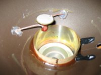
I am not that familiar with their products…wondering if it was anything like this pic of an older Genesis 12B woofer.
Audio Asylum Thread Printer
The mounting looks a little precarious to me perched on a stick mounted to the VC.
But then again, I guess it would deter vibration from cone break modes finding their way to the accelerometer.
Attachments
Respectfully disagree.
It is assumed the VC impedance represents the velocity of the cone (corrected as needed for static parameters) and assuming the cone sort of behaves nice like a piston. Now piston behaviour is an assumption shared by all in all MF implementations unless done with a mic.
Then "reading" the reference point (where the 4-Ohms meets the driver) and, by means of the Sigma Drive feedback, keeping it a constant voltage gives you a voltage at the driver reflecting inversely (AKA correctively) the motions of the cone (including true motions and all false motions). That reference point is a voltage divider and that is why it "reads" the impedance and corrects for deviations in the impedance arising from the back-EMF of false motions.
(The Genesis woofer does not look very elegant, as Retsel mentions. Of course as Retsel mentions, MF corrects for many manufacturing shortcomings and lets the manufacturer cut corners. Or you could work with VC MF using the kind of high-class driver loved around here. A lot of the patented work was done by manufacturers who wanted to put a "quart of milk into a pint pot" rather than the DIYaudio crowd who want the last bit of quality using quality parts.)
Right?
Ben
Last edited:
Yes, it keeps it at a constant voltage.…"reading" the reference point (where the 4-Ohms meets the driver) and, by means of the Sigma Drive feedback, keeping it a constant voltage gives you a voltage at the driver reflecting inversely (AKA correctively) the motions of the cone (including true motions and all false motions)
No, the voltage at the driver does not reflect inversely the motion of the cone…remember it is held constant.
The back-EMF from the drive does change the load impedance and thus the voltage drop across the 4 ohm resistor.
The feedback loop modulates the amplifier output to compensate and keep the voltage at the driver constant.
In other words, the voltage output of the amplifier is modulated inversely to the back-EMF such that the voltage applied to the driver is constant.
As mentioned previsously, the Sigma remote sensor circuit was designed to drive the woofer with a constant amplitude signal irrespective of the impedance of the connecting wires, thus emulating a perfect voltage source not MFB.
Volume
"It is remarkable that a 7" in a 4 litre box does sound similar to a 12" in a 40 litre box using MF. "
Can anyone confirm this volume?
During my research I read conflicting information 4 litres to 13...
Which one is true? Also what kind of internal damping was used?
(cotton, wool, fiberglass, or foam?)
.
It has taken me four years and 24 days, but I now understand our difference and why someone might not see Sigma Drive as MF.In other words, the voltage output of the amplifier is modulated inversely to the back-EMF such that the voltage applied to the driver is constant.
As mentioned previsously, the Sigma remote sensor circuit was designed to drive the woofer with a constant amplitude signal irrespective of the impedance of the connecting wires, thus emulating a perfect voltage source not MFB.
The purpose of remote sensing, like Sigma Drive, is to ensure the voltage at the speaker or driver terminals is constant despite losses (if much at all) in the space between the speaker and the amp. As you nicely point out.
Remote sensing is made available against the possibility of losses in the wires. If there are losses, then the signal at the speaker (and consequently the sound output) will vary with the dramatically varying impedance of the speaker or driver. The Sigma Drive counter-acts that and therefore, it is a form of motional feedback. It is reacting to the varying back-EMF of the driver(s) not the unvarying feedback signal from the resistance of the wires. BTW, that "varying feedback" includes distortion in the motion of the driver(s).
Also, the remote sensing ensures the extremely high damping factor of a modern amp is applied to the speaker terminals, not lost to losses. Which is another way to think of motional feedback benefits. Of course, for "real" motional feedback the damping factor goes through zero and becomes negative not large but positive.
Anyone who is new to MF should think about how a woofer would be misbehaving at resonance with impaired damping (the third paragraph) and the concept in the fourth paragraph with negative damping.
Since there just isn't much resistance in the wires usually, the Sigma Drive doesn't have much impact or reduce distortion much. But it still have can have a big effect on today's monumental DFs albeit of no audible benefit.
B.
Last edited:
"It is remarkable that a 7" in a 4 litre box does sound similar to a 12" in a 40 litre box using MF. "
Sadly, some manufacturers over the years have introduced MF as a great way to get impressive sound out of small subs for big markets. It sure is.
But most of us at DIYaudio want to get the greatest sound feasible from right-sized boxes. So it hardly makes DIY sense to devote all that sweat to making a little box OK.
B.
+1Reduction in dipole woofers will be just as good as in sealed boxes. It is actually in dipole it would be most attractive to use servo since low frequency SPL requires a lot of excursion on dipoles
OB/dipole meets the MF criterion of the sound "resembling" the motion of the cone (unlike systems with tuning where the tuning changes that). So it can do its magic.
I suppose that MF would protect a dipole from excessive excursions (just as it does at resonance in a sealed box). But for a sealed box, you sometimes put the excursion back in with EQ (or acceleration) so the sound output is flat. If you did that as a kind of Linkwitz Transform with a dipole, the protection vanishes.
MF makes more sense with a nice clean sealed box which you can then push an octave lower and still be clean and "fast".*
B.
*OK, I'm making a logical mistake if we are talking about the same driver in a sealed box or OB where the same excursion in one is OK but not in the other where it is louder.
Last edited:
I have built several MF subwoofers in sealed boxes in the nineties. But later i went to OB together with my esl 63, since it integrates much better. I´m using double Dayton 15" IB per side. From 27 to 150Hz. 14-27 Hz is managed with 4 15" woofers in the wall between listening room and my garage. Since the room is big, the output from only the dipolewas coloured. So... thats why I look into MF again, just wanted to hear some peptalk about the distortion reduction. And hopefully see some figures ")
- Status
- This old topic is closed. If you want to reopen this topic, contact a moderator using the "Report Post" button.
- Home
- Loudspeakers
- Subwoofers
- Analog Servo Sub