The CS-30 is tuned around 34 Hz, if that is a high tuning, what do you consider low ;^)?Admittedly, these are actually less of a factor in a design like the CS-30, where there's a high tuning. (Since port compression becomes a bigger problem at lower frequencies.)
Do you have a link to the paper wherein they describe the math for determining the ideal dimensions for such a de Laval-style vent?Looking at the cabinet design, it is obviously a single ported cabinet. The port design has been described in JBL white papers, it reduces turbulence at high port velocity.
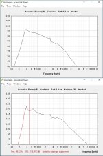
As far as the impedance response, it does look odd for a cabinet that is ported.
As you can see in the comparison of a Lab 12 in an oversized (underdamped) box and the CS-30 below, the Lab 12 Fb is higher, but they both have very similar phase and magnitude response above Fb.
Art
Do you have a link to the paper wherein they describe the math for determining the ideal dimensions for such a de Laval-style vent?
Maximizing Performance from Loudspeaker Ports* - Audio ...
www.aes.org/e-lib/download.cfm?ID=11094&name=harman
The paper has some math, but to quote from the article:
"The main difficulty in modeling flared loudspeaker ports is the infinite variety of profiles that will yield the same port tuning. Many loudspeaker designers choose not to experiment with flared ports because without a well- defined diameter to plug into the standard port tuning formula, they are left to design by trial and error. There are no CAD programs that incorporate the ability to design flared ports as of yet. However, there is a growing demand to take advantage of flared ports and a need for predicting their performance."
This statement was certainly reinforced by my most recent empirical quick and dirty port study, the response in post #7 surprised me, and does not fit any model I've seen, though emulates the CS-30 pretty well as far as frequency and phase response.
Art
Last edited:
Not even Akabak?Maximizing Performance from Loudspeaker Ports* - Audio ...
www.aes.org/e-lib/download.cfm?ID=11094&name=harman
The paper has some math, but to quote from the article:
"The main difficulty in modeling flared loudspeaker ports is the infinite variety of profiles that will yield the same port tuning. Many loudspeaker designers choose not to experiment with flared ports because without a well- defined diameter to plug into the standard port tuning formula, they are left to design by trial and error. There are no CAD programs that incorporate the ability to design flared ports as of yet. However, there is a growing demand to take advantage of flared ports and a need for predicting their performance."
This statement was certainly reinforced by my most recent empirical quick and dirty port study, the response in post #7 surprised me, and does not fit any model I've seen, though emulates the CS-30 pretty well as far as frequency and phase response.
Art
Try it and see if it matches what you build.Not even Akabak?
Maximizing Performance from Loudspeaker Ports* - Audio ...
www.aes.org/e-lib/download.cfm?ID=11094&name=harman
The paper has some math, but to quote from the article:
"The main difficulty in modeling flared loudspeaker ports is the infinite variety of profiles that will yield the same port tuning. Many loudspeaker designers choose not to experiment with flared ports because without a well- defined diameter to plug into the standard port tuning formula, they are left to design by trial and error. There are no CAD programs that incorporate the ability to design flared ports as of yet. However, there is a growing demand to take advantage of flared ports and a need for predicting their performance."
This statement was certainly reinforced by my most recent empirical quick and dirty port study, the response in post #7 surprised me, and does not fit any model I've seen, though emulates the CS-30 pretty well as far as frequency and phase response.
Art
Hi Art,
Just adding a few links to similar information, i.e. The 'Math' for a Nozzle ports and more, Good to have links to good 'Papers' gathered at the same location.
Vented-box geometry and low frequency reproduction: the aerodynamical approach
AES E-Library Vented-box Geometry and Low Frequency Reproduction: The Aerodynamical Approach
Sound source design in the very low frequency
domain.
AES E-Library Sound Source Design in the Very Low Frequency Domain
APPROXIMATIONS TO THE DIRECTIVITY INDEX
http://www.dtic.mil/dtic/tr/fulltext/u2/778660.pdf
b
")
PS: Adding my Notes (Picture):
Attachments
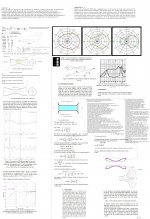
I took the images available online and 'reverse engineered' the box. This is what I came up with.
The image is a bit small, but the important dimensions are in the port. Here are the details:
- The end of the port terminates in a slot vent that's 7.62cm tall by 34.29cm wide.
- The vent narrows to a dimensions that's 3.8cm tall. That segment of the vent is 25.9cm long.
- The vent then begins to widen as we go towards the lower right corner of the sub. That segment of the vent is 17.27cm long. At the lower right corner of the sub box the vent height is 10.2cm.
- The final segment of the vent is 10.2cm long. The vent height at the final segment is 12.7cm. Note that the vent turns 90 degrees.
I would say you have left out an internal baffle that may be important in making this a double chamber box, see a sketchup model here:
Danley Sound Labs CS30 | 3D Warehouse
I do not expect the port to produce any band pass magic, other than it will show less compression than a flat slit port.
hi guy,
after being a passive reader for quiet a white, it's time to share something For quiet a while I try to fold my brain around the the concept of the cs30 and learn some new things. So what I did so far:
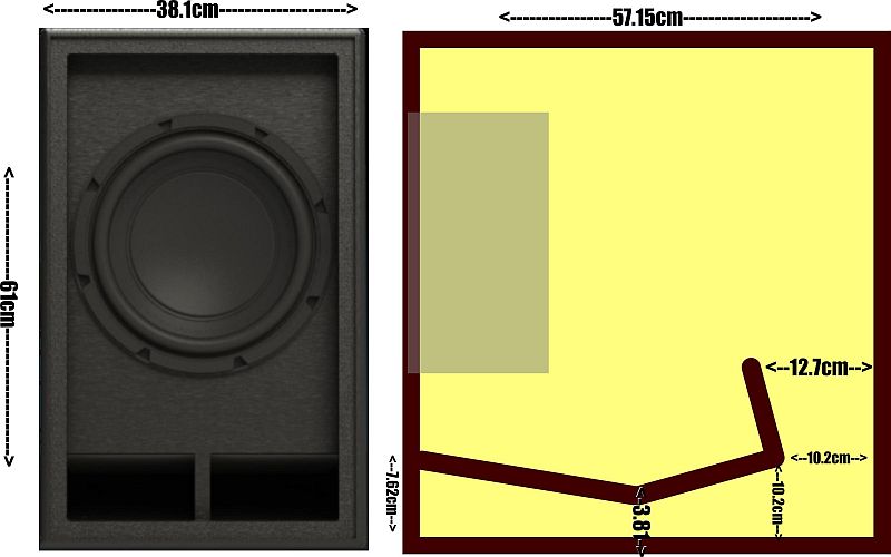
- Measured the wireframe weltersys posted in #7 and unfolded the port (tried my best reversing with the advanced center line method - but I must admit that I'm not 100% sure if I got that right)
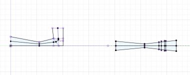
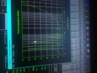
- Thew all that data in Hornresp and the resulting curves look more or less like what Patrick posted 8 years back
- After using the measured TSPs of StainlessSteve that include lossy le (Thread for Drivers with Semi Inductance) the response looks a little more flat
So that doesn't look to bad after taking into account that hornresps peaks are a little more flat in reality. One of my ideas was that in reality the port appears to be longer than it is in the simulation because of the the "extension" of in on the floor and the back of the cabinet.
What I don't get is how Danley gets that maximum output rating of 121db with a operating frequency range between 33hz and 67hz. Does anyone know how this is measured? The max spl graph shows a dip with 119db at 49hz.
max
after being a passive reader for quiet a white, it's time to share something
For quiet a while I try to fold my brain around the the concept of the cs30 and learn some new things. So what I did so far:- Measured the wireframe weltersys posted in #7 and unfolded the port (tried my best reversing with the advanced center line method - but I must admit that I'm not 100% sure if I got that right)
- Thew all that data in Hornresp and the resulting curves look more or less like what Patrick posted 8 years back
- After using the measured TSPs of StainlessSteve that include lossy le (Thread for Drivers with Semi Inductance) the response looks a little more flat
So that doesn't look to bad after taking into account that hornresps peaks are a little more flat in reality. One of my ideas was that in reality the port appears to be longer than it is in the simulation because of the the "extension" of in on the floor and the back of the cabinet.
What I don't get is how Danley gets that maximum output rating of 121db with a operating frequency range between 33hz and 67hz. Does anyone know how this is measured? The max spl graph shows a dip with 119db at 49hz.
max
Attachments
Last edited:
Max,What I don't get is how Danley gets that maximum output rating of 121db with a operating frequency range between 33hz and 67hz. Does anyone know how this is measured? The max spl graph shows a dip with 119db at 49hz.
The operating range of 33Hz- 67Hz is specified at the -3dB points, the dip of approximately 1.25dB around 50Hz is ignored.
The CS-30 response curve is not a "maximum output" measurement, it is the response measured using 28.3V @ 10M, equivalent to 95 dB with 2.83v input at 1 meter.
2.83 volts is equivalent to one watt into 8 ohms.
"Maximum Output" of 121 dB SPL is simply math:
95dB @ 1watt
105 dB @ 10 watts (+10dB)
115 dB @100 watts (+10dB)
118 dB @ 200watts (+3dB)
121 dB @ 400watts (+3dB)
As usual, the math ignores power compression due to voice coil impedance rising when hot.
Art
hi guy,
after being a passive reader for quiet a white, it's time to share something
- Measured the wireframe weltersys posted in #7 and unfolded the port (tried my best reversing with the advanced center line method - but I must admit that I'm not 100% sure if I got that right)
- Thew all that data in Hornresp and the resulting curves look more or less like what Patrick posted 8 years back
- After using the measured TSPs of StainlessSteve that include lossy le (Thread for Drivers with Semi Inductance) the response looks a little more flat
So that doesn't look to bad after taking into account that hornresps peaks are a little more flat in reality. One of my ideas was that in reality the port appears to be longer than it is in the simulation because of the the "extension" of in on the floor and the back of the cabinet.
What I don't get is how Danley gets that maximum output rating of 121db with a operating frequency range between 33hz and 67hz. Does anyone know how this is measured? The max spl graph shows a dip with 119db at 49hz.
max
For the most part, I think the CS30 is a QB5 box. There's some formulas for sizing them here:
Satellites and Subwoofers
If you run some sims with them, the alignment can produce a fairly ridiculous amount of output, once you design the filters carefully.
Group delay is only as big as you make it.
Drag a driver into the uncomfortable area of pressure in its environment.
as soon as youre outside of that window you have it. (And its not at the port). Its at any ‘port’ and its relation to another, or the other end of it. As in the driver or the fold or the chamber <z>??
But what is its real cause? Or what is going to prevent it?
Keeping those all at harmonic intervals between or doubled up ones inbetween(the pressure nulls).
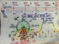
Why a ‘TL’ is somewhat ‘easier’ to get away with bass. Its probably folded as and even split up as its own odd harmoincs. and even the compounded or offset stubbed versions with be required to abide by tgat orugin pipes Fb and its odd harmonic pressure null defined (0.349 seems to be the most popular and easiest to ride out usinfmg the entire system based on it.
If you pick the wrong Fs for Fb. Its not the pipe harmonics fault. But they get blamed? Hows the pic? I tried to put a good spin on that idea
Drag a driver into the uncomfortable area of pressure in its environment.
as soon as youre outside of that window you have it. (And its not at the port). Its at any ‘port’ and its relation to another, or the other end of it. As in the driver or the fold or the chamber <z>??
But what is its real cause? Or what is going to prevent it?
Keeping those all at harmonic intervals between or doubled up ones inbetween(the pressure nulls).
Why a ‘TL’ is somewhat ‘easier’ to get away with bass. Its probably folded as and even split up as its own odd harmoincs. and even the compounded or offset stubbed versions with be required to abide by tgat orugin pipes Fb and its odd harmonic pressure null defined (0.349 seems to be the most popular and easiest to ride out usinfmg the entire system based on it.
If you pick the wrong Fs for Fb. Its not the pipe harmonics fault. But they get blamed? Hows the pic? I tried to put a good spin on that idea
Attachments
Last edited:
And switch it up in only one way in each example to ‘create’ it.
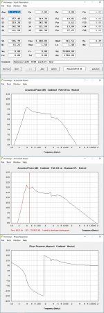
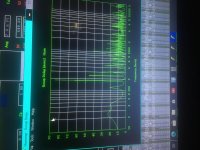
This is the difference in the drivers qes. Green is a false .6 white was its real .32. Nothing else has same-exact enclosure... but the Le feature is the mechanism. Intentionally provoking the ambiguity of cause and affect maybe?
This is the difference in the drivers qes. Green is a false .6 white was its real .32. Nothing else has same-exact enclosure... but the Le feature is the mechanism. Intentionally provoking the ambiguity of cause and affect maybe?
Attachments
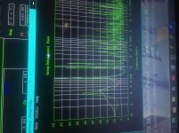
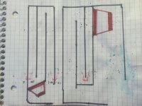
Here ive moved the driver within that harmonic interval, but ive already used it on the polar opposite of the driver output(rear vented 80 cm, front qw pipe 80cm x 3, white. Then green i placed another above the qw pipe at 80cm. That might sound as if im tuned too low as a result ? And its correct, but its not the only issue. because if i split that 240cm up in another way thats still 240 cm(160 and 80, or 80 +80 + 80) instead or 120 cm and 120cm i get a disaster in GD. (Next pic)
Attachments
Here. The sim is no longer 240cm (as 120/120 folded) its 160/80...
So what does that mean? the sim does not see folding, or the folding is more important then anything and can be excessive contributions to the same area of the BW and floods it into a gap in response or a spike in one turn of the ‘timing’ prior?
Hopefully that makes sense. Id draw it but its just as hard to type it to try and share/convey the idea...i think it gets very confusing looking quickly as full wave, over a qw and the harmonic 3 and 5 thru all of that. but the pressure nodes can be seen as phase as 90/180/-90(270), 360(zero) and out to 450(90),540(180,-180,0),630(270/-90/90), 720(0,360 and 180). That must line up and in every ‘offset’ or ‘compound’ and at the 0.349 portion of the ‘main’ Fb being applied to the transducer at the correct cross section for Vas and length in respect to (Fs/Qts) ?? Gotta trase the brain looking at a log scale half the time and then asking ‘where’ its at in a length vs freq... hurts my little pea brain
Yes or heck no!! Get outta here?
Attachments
Last edited:
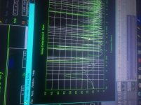
Move that driver (blue) or put it in a rear pipe, or shift its position in the long one by adding another interval (80cm is 90 degrees affectively) and you define exactly what you can or cannot do at those. Assuming the pipes or direct radiator/pipe are concentric at exit of pipe or occupy the exact position) so to speak.
Tapped pipe sim being offset here by the rear chamber entry of 80 cm in in the pics above).
Tapped pipe sim being offset here by the rear chamber entry of 80 cm in in the pics above).
Attachments
Last edited:
These two are either spot on or a huge disaster in the way a person ends up creating them and the driver. Its is exactly on the harmonic interval from any place (other /added) to the original long pipe and direct radiators 90 degrees in a straight plain imaginery pipe that will dictate all things thereafter?
It ‘feels’ as such, having screwed around with both enough too figure them out enough to come full circle (again) and realize in no way possible will i ever really truely ‘know’ anything!!! its all far to amazing to digest and keep it as such?
Even the drawing will misstepresent the exact idea in reference. Because it is infinity from exact. But after 5 harmonics or maybe 9?(9/4?) can we just ignore the corners, the driver radius, the port centerline..... after all, 5 halflives in a radioactive isotope and its all good? Thats enough ‘ignore’ 5 decades to me? Hopefully a sound wave decays faster then its harmonics though or its horrible isotope , LOL?!!!
Attachments
Last edited:
- Status
- This old topic is closed. If you want to reopen this topic, contact a moderator using the "Report Post" button.
- Home
- Loudspeakers
- Subwoofers
- Featherweight Title Fight