The wife has been bugging me to create a more "incognito" subwoofer for the A/V system in auxilliary home theatre/living area. So I purchased a pair of spunky little 6.5 inch drivers from PE for 9 dollars a piece. The specs are here
6-1/2" Subwoofer Speaker
This 6-1/2" subwoofer speaker features a deep profile, long fiber, high-pulp cone finished beautifully in a protective coating that also dampens resonances. The 1-1/2" diameter 4-layer voice coil's 5/8" winding length maintains plenty of copper in the magnetic gap, ensuring plenty of high-impact, low-distortion output. A vented pole piece reduces performance-robbing power compression, and the magnet structure's extended back plate prevents "bottoming out" the long voice coil. Great subwoofer speaker for any design or application, particularly multimedia systems, small home theater setups, and multi-driver configurations. Buyout, limited quantities.
Specifications: *Power handling: 80 watts RMS/160 watts max *VCdia: 1-1/2" *Le: 1.61 mH *Impedance: 4 ohms *Re: 3.25 ohms *Frequency response: 35-2,000 Hz *Fs: 38 Hz *SPL: 83.5 dB 1W/1m *Vas: 0.55 cu. ft. *Qms: 6.74 *Qes: 0.64 *Qts: 0.59 *Xmax: 4.5 mm *Dimensions: Outside diameter: 6-1/2", Cutout diameter: 5-3/4", Depth: 3".
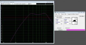
I modeled these drivers together and it looks like a dual chamber, 6th order bandpass design yieilds great results.
.5 cubic foot tuned to 80hz front chamber, 1.5 cubic foot rear chamber tuned to 35hz. Nice 3-4 DB of gain between relatively flat passband of 32-110 hz.
FWIW, she wanted me to purchase bose acoustamas system because it hides so easiy. This is why I decided to build the 6th order with smaller drivers.....to show that I can design and build a better sytem on the cheap.
I will be building my own "cubes" out of Tang Band 3 inch aluminum cone drivers.....
Looking at the specs of these drivers, do you think the 6th order will provide decent sound quality for some non critical listening. I am open to other off the wall designs if anybody has any suggestions.
6-1/2" Subwoofer Speaker
This 6-1/2" subwoofer speaker features a deep profile, long fiber, high-pulp cone finished beautifully in a protective coating that also dampens resonances. The 1-1/2" diameter 4-layer voice coil's 5/8" winding length maintains plenty of copper in the magnetic gap, ensuring plenty of high-impact, low-distortion output. A vented pole piece reduces performance-robbing power compression, and the magnet structure's extended back plate prevents "bottoming out" the long voice coil. Great subwoofer speaker for any design or application, particularly multimedia systems, small home theater setups, and multi-driver configurations. Buyout, limited quantities.
Specifications: *Power handling: 80 watts RMS/160 watts max *VCdia: 1-1/2" *Le: 1.61 mH *Impedance: 4 ohms *Re: 3.25 ohms *Frequency response: 35-2,000 Hz *Fs: 38 Hz *SPL: 83.5 dB 1W/1m *Vas: 0.55 cu. ft. *Qms: 6.74 *Qes: 0.64 *Qts: 0.59 *Xmax: 4.5 mm *Dimensions: Outside diameter: 6-1/2", Cutout diameter: 5-3/4", Depth: 3".
I modeled these drivers together and it looks like a dual chamber, 6th order bandpass design yieilds great results.
.5 cubic foot tuned to 80hz front chamber, 1.5 cubic foot rear chamber tuned to 35hz. Nice 3-4 DB of gain between relatively flat passband of 32-110 hz.
FWIW, she wanted me to purchase bose acoustamas system because it hides so easiy. This is why I decided to build the 6th order with smaller drivers.....to show that I can design and build a better sytem on the cheap.
I will be building my own "cubes" out of Tang Band 3 inch aluminum cone drivers.....
Looking at the specs of these drivers, do you think the 6th order will provide decent sound quality for some non critical listening. I am open to other off the wall designs if anybody has any suggestions.
Permo,
I see you missed a project that has been ongoing for a while now, using the PE 6.5 buyout woofer.
Start here, scrole back to about post #50, there are plans, sims, and construction pics.
It is a nice little deal on a driver; a bit on the light side, although my HT never sounded better....using 2 double boxes, 8 woofers.
http://www.diyaudio.com/forums/subwoofers/203345-isobaric-less-then-20-a-26.html
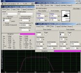
4th order isobarik bandpass eh....? I will load up winisd tonight and play around with that idea.
Is 6th order iso bandpass just a bad idea? I found with a single driver, the 6th order modeled a whole lot better. I have small mains for this project and I need usable output to 110 hz or so.....
Heck, 4th order iso I bet I could get down to a cubic foot total. That would be SWEET.
Is 6th order iso bandpass just a bad idea? I found with a single driver, the 6th order modeled a whole lot better. I have small mains for this project and I need usable output to 110 hz or so.....
Heck, 4th order iso I bet I could get down to a cubic foot total. That would be SWEET.
Hi permo,
Could you, please, post your driver parameter input screen for WinISD. I cannot find a good correlation between what I entered into WinISD and Hornresp.
Hi ODougbo,
What would the equivalent air duct length be to the 10" PR, or , what would the moving mass of the PR be? I have not come up with anything that I would consider workable. Maybe the PE 264-1060:http://www.parts-express.com/pe/showdetl.cfm?Partnumber=264-1060
Regards,
Last edited:
The 1.2cf Iso test box started off with 2 - 1.5" PCV x 10" vents. From there I went to the 10" PR, 50 grams (but it called for 70grams).
If I remember right, I modeled it with an 8"PR and a 12"PR (PE low cost units); the 10" PR looked the best.
The 10" PR retrofit was the better box.
If I remember right, I modeled it with an 8"PR and a 12"PR (PE low cost units); the 10" PR looked the best.
The 10" PR retrofit was the better box.
Hi Y'all,
I don't know if you have found "Bagby's Woofer and Circuit Designer" yet, its great for passive radiator designs, and you can always cross-check with your favorite design software for a sanity check.
Loudspeaker Design Software
I entered the PE 299-114 isobaric pair into Bagby's together with the PE 295-494 10" PR, and it indicates that w/ 51gm added mass it has a peak at about 72Hz (nice(?) triangluar shaped SPL curve); w/ 150gm the peak has shifted to 44Hz-and the shape is a little less triangular; w/ 276gm the response is flat from about 30-70Hz; w/ 426gm the response starts sloping slightly at the lower end being ~12dB down @ 20Hz (which might play nice with the room gain in a corner). All this is w/ a 1st order high pass set @ 25Hz to keep the excursion below the tuning point under control, Xmax is reach @ 20W, SPL @ that wattage about 90-93dB.
A design like this would probably take a 14" cube to build.
I would be great if one of you could actually measure the T/S parameters of these woofers, as building something like this, or-even worse-a BP6 will require getting the parameters correct.
Regards,
Hi permo and ODougbo,
I finished the first cut at sketching out a BP6 for the 299-114 (see: Post #11 for WinISD). Size: 19.5" x 14" x 14". It gets to be a bit convoluted, but not much more than any folded duct enclosure. No it's up to the woodworms.")
Regards,
I finished the first cut at sketching out a BP6 for the 299-114 (see: Post #11 for WinISD). Size: 19.5" x 14" x 14". It gets to be a bit convoluted, but not much more than any folded duct enclosure. No it's up to the woodworms.
Regards,
Attachments
Hi again,
I use AutoCAD for the drawing, and plot the output to PrimoPDF.
There are two chambers Vf on the left, and Vr on the right. There two ducts, one for each chamber, making it a 6th order bandpass; both duct bend around, and then up into their respective chambersw. In the top view of the duct section the lower duct (Lv_f) vents Vf, and the upper duct vents Vr. I tried to get as close to the WinISD values as I could, and guessed at an end correction of about 2" for each duct. The waste volumes around the ducts are vented into the Vf and Vr chambers respectively, and are accounted for in the design (but not that critical). The design allows for the end boards to be removable (this may take some blocking on the side where the ducts vent).
As so often, it looks more complicated than it is, just a lot of small pieces in the duct section. I made all the little internal divider boards from 1/2", and the larger external boards (and the driver mounting baffle) from 5/8". You can change those dimensions as long as you get the internal duct dimensions correct. If you need any other printouts let me know.
As always, especially with a BP6, we hope the T/S parameters are correct.
Regards,
Last edited:
Oliver, what do you think about using two of the drivers in a standard or even push pull (non iso) configuration? I am concerned about the output and sensitivity of the isobarik design. If I keep the design in the 2-3 Cubic foot range I would be perfectly satisfied.
I am only going to have about 150 watts to throw at it, so efficiency will be paramount for me again.
I really like your side by side with the ducts below design.....
I am only going to have about 150 watts to throw at it, so efficiency will be paramount for me again.
I really like your side by side with the ducts below design.....
- Status
- This old topic is closed. If you want to reopen this topic, contact a moderator using the "Report Post" button.
- Home
- Loudspeakers
- Subwoofers
- 6th order bandpass design for dual 6.5"