I found someone was having a special on a pair of Peerless 830855s (don't remember who). It's the smallest driver I've ever seen described, by the manufacturer, as a subwoofer - 4"!
http://www.tymphany.com/files/SDS-P830855%20Rev1_0.pdf
The idea of a 4" subwoofer intrigued me and I figured I could use them for my computer.
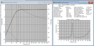
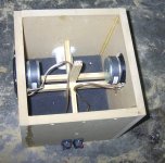
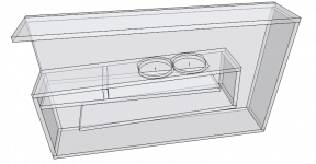
I measured impedance with Dayton's WT3, and modeled them with Audua's Speaker Workshop (I never trust manufacturer's specs). Even though Tympani's data sheet said they're ideal for sealed boxes, SW modeled a much better response for a pair in a 14.3 liter ported enclosure tuned to 53Hz. As you can see in the photo, I put them on opposite ends of the same 14.3 liter cube with a single port, even though they will be driven by separate amplifier channels. After building it I was disappointed with the very loud chuffing, and a loud resonance when playing a 45Hz test tone.
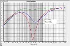
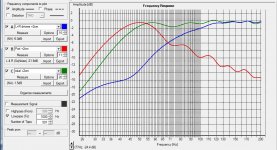
Next day, I did some nearfield measurements of both drivers, and of the port with Holm Impulse. The two drivers were driven by separate channels being fed the same signal. I had to take time-aligned measurements of the two drivers separately, sum them, then sum that response with the time-aligned port response, all in Impulse. I then taped an extra 1cm, 2cm and 3cm on the end of port and repeated the measurements. I got a much nicer response with an additional 2cm on the port. I was a bit surprised because usually SW's calculations are spot-on.
All-in-all I'm impressed with what Peerless can get a 4" woofer to do. Some people may be wondering whether or not they can be used as a full range driver. I would not recommend it. I listened to some music, and thought the mids were pretty muffled.
This project got me wondering just what a subwoofer is. That is: how does a driver described as a "subwoofer" differ from the same size driver described as just a "woofer". Is it their inability to play mid bass, and a need for a low X-over point? Just wondering if anyone has any ideas.
http://www.tymphany.com/files/SDS-P830855%20Rev1_0.pdf
The idea of a 4" subwoofer intrigued me and I figured I could use them for my computer.
I measured impedance with Dayton's WT3, and modeled them with Audua's Speaker Workshop (I never trust manufacturer's specs). Even though Tympani's data sheet said they're ideal for sealed boxes, SW modeled a much better response for a pair in a 14.3 liter ported enclosure tuned to 53Hz. As you can see in the photo, I put them on opposite ends of the same 14.3 liter cube with a single port, even though they will be driven by separate amplifier channels. After building it I was disappointed with the very loud chuffing, and a loud resonance when playing a 45Hz test tone.
Next day, I did some nearfield measurements of both drivers, and of the port with Holm Impulse. The two drivers were driven by separate channels being fed the same signal. I had to take time-aligned measurements of the two drivers separately, sum them, then sum that response with the time-aligned port response, all in Impulse. I then taped an extra 1cm, 2cm and 3cm on the end of port and repeated the measurements. I got a much nicer response with an additional 2cm on the port. I was a bit surprised because usually SW's calculations are spot-on.
All-in-all I'm impressed with what Peerless can get a 4" woofer to do. Some people may be wondering whether or not they can be used as a full range driver. I would not recommend it. I listened to some music, and thought the mids were pretty muffled.
This project got me wondering just what a subwoofer is. That is: how does a driver described as a "subwoofer" differ from the same size driver described as just a "woofer". Is it their inability to play mid bass, and a need for a low X-over point? Just wondering if anyone has any ideas.
Attachments
Last edited:
 That's a curious glitch that Speaker Workshop has. I didn't use the sealed box method for calculations. I used the added weight method. But SW puts that value in the driver description anyway. I didn't build a 35^3 speaker cabinet.
This project got me wondering just what a subwoofer is. That is: how does a driver described as a "subwoofer" differ from the same size driver described as just a "woofer". Is it their inability to play mid bass, and a need for a low X-over point? Just wondering if anyone has any ideas.
I think it depends on what the marketing department needs to sell more of.

I always thought of sub-woofers as just that, a driver with a Fs 20-30Hz that filled in below the woofers (~60Hz). But I'm just an old IATSE sound engineer, most of my career I only used Subwoofers for "effects" so what would i know.
later,
rev.
Hey Byron, I remembered seeing these Tang Band subs in a PE flyer and thought you might be interested. Maybe it's the upper freq response that is used to categorize subwoofers? I'm also intrigued by little subs that can provide usable output <50Hz. Looks like a neat PC multimedia box you've put together. Where did you set the LPF?
.. a neat PC multimedia box ..
Hi,
FYI, A less than 1 liter box suggestion using two TB-W2-1625SA:
b
Attachments
Now that is TINY is the driver gonna fit?
Good observation,Yes they should fit as I can see if the the drivers are mounted in reverse,i.e. with visible magnets.
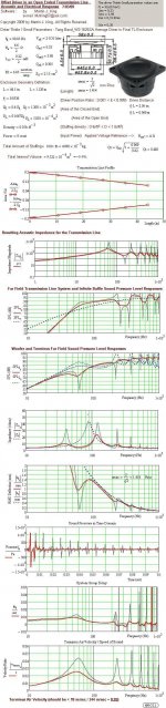
Complementing the HR picture with an MJK simulation showing that the stuffing is essential for good performance:
b
Attachments
Where did you set the LPF?
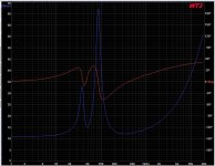
- The impedance curves say the box tuning frequency is ~50Hz, and the vent tuning frequency is just under 40Hz.
- The calculations from Vance Dickason's book say the box tuning frequency is ~47Hz - close enough.
- the nearfield recording of the port peaks right at 50Hz. I guess it's supposed to peak at the box tuning frequency, not the vent tuning frequency. I don't know.
This is the first time good ole' Audua has given be a bad model. I'm guessing it has something to do with the way I powered the woofers. When modeling dual-woofer enclosures, Speakerworkshop asks if the drivers are in series or in parallel, and tells me to use different tuning frequencies/ vent lengths depending on which I choose. But I'm not wiring them in series or in parallel. I have a separate amp channel driving each driver. I also wonder if maybe there is a phase difference between left and right channels in my D/A converter (Behringer UCA222). That would really mess things up!
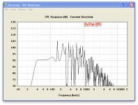
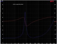
The last picture just shows that if I test the impedance of the subwoofer with the drivers out-of-phase the impedance peak from the port disappears - which makes sense. Not really informative, I just tried it out of curiosity.
-Byron
Attachments
- Status
- This old topic is closed. If you want to reopen this topic, contact a moderator using the "Report Post" button.
- Home
- Loudspeakers
- Subwoofers
- World's smallest subwoofer?