Can't edit my post, seems like my drawing is bad once again but :
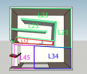
- L12 actually starts at the middle of the driver, so =~27,5cm
- L45 extend to the end of the horn, that's where it gains some length and then =~36.5cm
I think it's because you can't add a S6 and the last expansion is so short, it doesn't affect that much the response and then it's negligible.
- L12 actually starts at the middle of the driver, so =~27,5cm
- L45 extend to the end of the horn, that's where it gains some length and then =~36.5cm
I think it's because you can't add a S6 and the last expansion is so short, it doesn't affect that much the response and then it's negligible.
Alright, it seems logic to me (I measured it as well) and would then result in the attached drawing, do you agree ?
One thing I don't understand is why Ricci's value of S1 is so low ?
Bigger the S1, bigger the dip at 89hz is in hornresp (if I put S1 = S2 like Brian Steele does on his workbook by example)
Thanks !
One thing I don't understand is why Ricci's value of S1 is so low ?
Bigger the S1, bigger the dip at 89hz is in hornresp (if I put S1 = S2 like Brian Steele does on his workbook by example)
Thanks !
Attachments

Alright, I understood it that way but thought the base file was made like THE Othorn
Can't obtain the same inputs as Ricci within the workbook, maybe doing it the wrong way but since S1 = S2 once you click "Optimize", I don't see any solution.
Anyway, it's not the "easy" modification I was looking for but it could be an awesome tool for someone who want to build an Othorn-style horn !
(And quite interesting to look at even if it's way too complex for me)
The workbook is actually pretty simple - just enter the box dimensions, the driver's parameters, a value for S1 and perhaps the panel widths (if you want to use different panel widths), and click Optimize until the error field shows zero. The workbook will adjust the dimensions of the panels in the horn until it's able to get a good fit for the box size requested. The required panel dimensions can then be pulled from the green box in the first spreadsheet in the workbook, and the layout of the panels is outlined on the "Guides" sheet.
I tried using the parameters for the original Othorn in the workbook, and the predicted result looks a lot like the MEASURED result that Josh got (see post #112 onwards). The dip around 90 Hz might be a bit deeper than the version with the extra panel at S1, but rest of the response curve is very similar.
The driver that you're trying to use has lower BL than the driver used by Josh, and it will perform differently in that enclosure.
I actually tried to put S1 = 20.5 in the workbook and couldn't reach 0 errors, that's why I was asking if '20.5' was a normal value, 403 looks more appropriate (and it doesn't affect that much the simulation anyway excepted on the 90hz dip)
Your tool is actually awesome but I don't want to take the time and the risk to modify everything.
The ideal (for me) would be to keep the Othorn plans and just add those 15centimeters of height on the last segment (from the bottom corner to the mouth).
Even if it's not the most optimized thing to do.
That's why I ask if my simulation (attached in post #500) seems ok to you, people with advanced knowledge.
And if not, what should I change to get closer to reality.
The only risk I'm taking is loading the future modded Othorn with a 21DS115-4 which has a lower BL, I saw somewhere a Ricci's post where he said it should be ok.
I can have the 21DS115-4 for 380€ whereas the 21SW152-4 is at 520€.
Considering I want 2 boxes, the 21DS115-4 saves me 280€, I'm ok with it even if I lose a bit of performance
If you go about increasing dimensions and changing drivers it is likely that the performance and behavior will also change and possibly not for the better. You could end up with a longer path length and even lower tuning. You may make the top end response a lot rougher, or create a high Q response peak. It's hard to say.
Small changes aren't a big deal but when you start modifying the length, throat area and expansion these are big changes.
S1 really was that small on the original. I diminish S1 on most of my designs for a few reasons. V2 as shown in your pics has a slightly different throat area and S1.
It's been a really long time since I posted the simulation for this design. It's accuracy could probably be improved a bit.
Alright, just watched out the v1 plans, that explain the low S1.
Unpredictable results then.
Just got one idea anyway, I'll add the 15cm to make my first Othorn but won't glue the bottom of it.
It will allow me to try it and measure it.
If it sounds good to my taste I let it like this and glue everything.
Otherwise I just have to cut the 15cm and then end up with the original Othorn
do you agree ?
Yes, your revised drawing is correct.
Depending upon the actual expansion profile, it may not be necessary to specify both L23 and L34. It may be possible to simulate the design using just three segments in total.
If L23 and L34 are required to more accurately specify the profile, then the boundary between the two segments may possibly be better placed at a different position to that shown. That is, L23 could be perhaps shorter and L34 longer, provided that the combined length of the two remains the same.
Attachments
Depending upon the actual expansion profile, it may not be necessary to specify both L23 and L34. It may be possible to simulate the design using just three segments in total.
Alright thanks ! At least it ended correct for the standard Othorn.
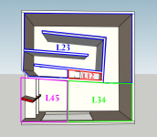
I could have put together L23 and L34 but considering I was going to edit L34 expansion (the complete horn was no longer expanding in a uniform way once I added the 15centimeters of height), it was easier for me to cut it in two
Didn't know where to calculate S3, took the easy way and measured it just before the bottom corner ahah.
If you leave the L23 expansion at PAR(abolic), the total volume of the sim'd horn will likely be larger than the actual volume of the horn. If you take a closer look at the layout of the panels for the L23 section, you'd see that the expansion does not remain the same from S2 to S3, a requirement for simming that section as a PAR section. I ran into this issue when trying to sim the Othorn some time ago.
Hey guys
Does anyone have a working autocad file for cnc purposes? I built 8 of these a couple of years back, and are now assisting my friend with his own small build. Unfortunately, Ive traveled between countries and forgotten my hard drives with all my files. The .dxf version that Josh linked up a few years back, isnt playing nice.
Any help appreciated ^_^
- Home
- Loudspeakers
- Subwoofers
- The Othorn tapped horn