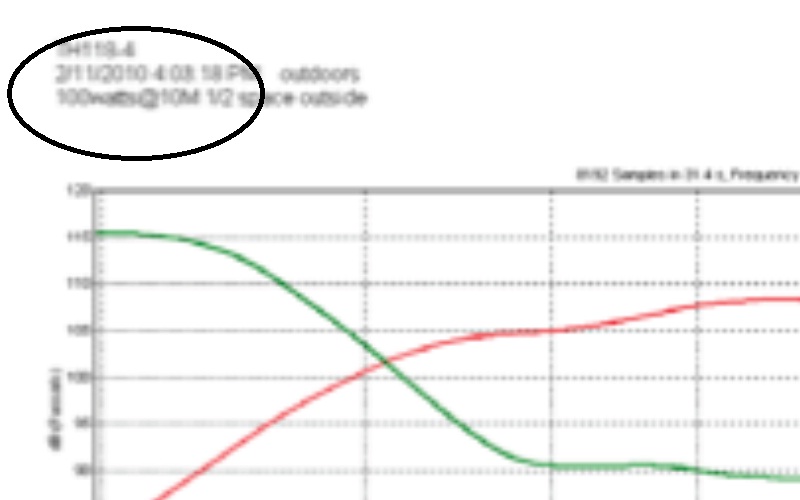
I applaud the use of 28.3v as a reference as it removes alot of ambiguity..... however even in the latest published spec that Tom just referenced. http://www.danleysoundlabs.com/danley/wp-content/uploads/2012/04/TH118-spec-sheet.pdf
The Text says 28.3V at 10M -- TEF graph says 100watts at 10M...
It's that pesky confusing watts and volts in the same spec page that kinda throws folks.
Hi jbell,
It indicates the 4Ω driver so that's incorrect, the last version is below. What I don't agree with so much is the TEF measurement setup, the low end of the FR in the measurements looks not like what I would expect for an upright single box 1/2 space measurement.
[sarcasm mode]Maybe the outside is also a typo, could be out beside the block building
 [sarcasm mode/]
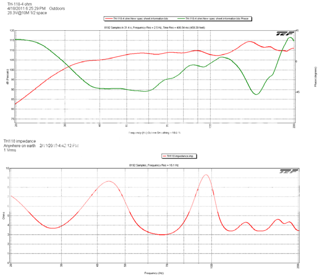
I always understood it to be 200w nominal, but the thing I wondered is could this be a 200w/40v sweep on the 8Ω driver, to me that would make sense as the 18SW115-8 has the better LF. DLS needs a tech in house to keep the marketing folks in check.
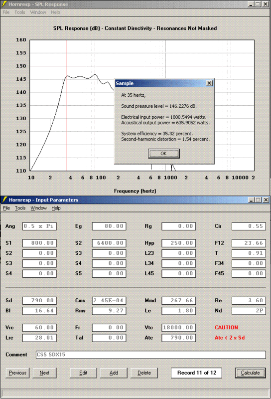
Hi Tom,I challenge anyone to come up with a Hornresp design that does 105dB @ 1W, or 108dB @ 2W for the range down to 40Hz. Short of making a 4m long, 2m wide fullsize horn, I don't think it's possible. So obviously I must be missing something, because I hardly believe that DSL would be lying.
I don't think anyone wants to move around a single 2m wide box so how about we break it down into some lower cost modules...
...  how about 6' wide:
Hi
Actually the specs are Voltage based, not an imaginary Watt;
http://www.danleysoundlabs.com/danley/wp-content/uploads/2012/01/DANLEY-SPECIFICATIONS.pdf
A response curve and impedance curve is also given so that one can see the sensitivity at a frequency of interest, its not just one number.
http://www.danleysoundlabs.com/danley/wp-content/uploads/2012/04/TH118-spec-sheet.pdf
Best,
Tom Danley
Hi Tom,
good to see you still reading here, in the years I've been on this forum, I've seen you intersperse quite a few gems of knowledge amongst your posts, and I appreciate that - thank you.
I am aware of the voltage base of your specs, and applaud that as well, though I can understand you would want to clarify that for anybody reading.
Also the decision to use 28.3V at 10m instead of 2.83V at 1m seems a reasonable idea, as it definitely puts you in the far field of the sub, and well away from any near field effects.
The reason why I myself mentioned the ambiguous wattage spec, is because you measure a "nominal 4Ω" load, or in other words a minimal impedance of 3Ω (as I can't find an impedance sweep, I'm guessing around 2.5Ω DC Re) using a 28.3V signal, which corresponds to a lot more than 100W throughout most of the bandwidth of the speaker.
This is not a problem as such, seeing as you state both impedance and voltage clearly, so one can adapt to such.
For fair comparison IMO, one should measure an 8Ω design at 40V/100m or 4V/1m, the latter of which would correspond to the hornresp input. But even accounting for this power difference due to impedance, I still can't manage to simulate these 108dB/2.83V/1m in any way. Not with any existing driver I've tried, not with changing the specs to make some kind of ideal imaginary driver.
I am kind of disappointed that so much info about the DSL designs have leaked, it seems both the driver and the fold pattern are known, I liked it better when they were just a mystery box that could do 108dB@2.83v/4Ω/1m, and there was still the notion, that by changing some parameter around, you could still tickle out an extra 3dB somewhere.
Now however, the main question for me seems to be how to explain the discrepancy between hornresp simulations and measured SPL curve.
If I can find a large enough field, I think I'll do some polar plots of my tapped horn, that might offer some insight. Might be a bit tricky in the city though, so if anybody wants to beat me to it, feel free.
Hi mwmkravchenko
We have a new website which is still an agonizingly slow work in progress, new measurements for all the products are not done yet and for example the one for the TH-118 is not done yet, there is no impedance curve shown yet.
The TH-115 might be a better one to look at as it has both the impedance and magnitude shown and is essentially the same enclosure.
The TEF machine measurements do at times look different than sequence based measurements as it has superior noise immunity and the jagged ups and downs (measurement grass) which goes away when you average a number of measurements, isn’t present.
The custom had been to use “Watts” as the frame of reference but that was based on a nominal impedance (either 4 or 8 ohms) but in commercial sound Voltage is now the preferred term as Voltage is very easy to measure while power is not.
Pull up the data sheet for a TH-115 which has a clearer curve and has the impedance curve. When a curve says 100W, it was made with 28Vrms. This cabinet has a 4 Ohm driver but notice the impedance curve is above 5 Ohms over most of its range and only dips to 5 around 80 Hz.
For an 8 Ohm driver, the minimum Z might be as low as 5.6 - 6 Ohms but 5 ohms is too low to call it nominal 8 ohms and too high to call it 4 ohms so it’s another reason we used voltage as the reference. We measure at 10 meters and 10X the normal voltage because the enclosures take up a fair amount of space in the near field so 10 meter measurements allow a much more accurate prediction for greater distances used in commercial sound.
The measurement resolution for the TH-115 is 3.5Hz, the curve smoothing is 18% which is about 1/5 -1 /6 octave (hearing resolution mid band is one Bark wide or about 1/6 octave. If one were to take the measurement with a typical sequence based system, there would usually be a fair amount “noise features” which are not actually present and go away with a number of averages.
The woofer measurements are taken in a large flat area near the shop, the microphone (an earthworks) and HP voltmeter are used along with the TEF to take the measurements.
Jwmbro, yes there has been a great interest in “what’s inside”, a few have arrived at a close approximation what’s inside too. The number of tapped horns in the DIY area (and a few companies now) is funny considering that also a number of people have suggested it is “the same as” the Transflex (a design I had never seen or heard of) but it is clearly different.
Perhaps they have not actually read that patent as the Transflex patent calls out that the efficiency is the same as the direct radiating drive and the driver can be mounted on the cabinet exterior.
With the Tapped horn the sensitivity can be 10dB or more greater than the direct radiating case as it is a horn and the throat and mouth dimensions are part of the design. A detail like that may not matter to some but does to the patent office.
Lastly, the strength of a computer model is only as great as it’s ability to predict what you measure from the real thing.
Even Akabak does not exactly predict what you measure from a Tapped horn or bass horns unless you add some extra elements and the hf behavior is rarely right. All of our products were built going back and forth between computer models and the wooden reality, adjusting the computer model to predict what is measured, a proper measurement trumps the computer model.
If interested in what we are up to and have facebook and headphones on the computer, go to the facebook site, go to “posts by others” hit “see all” and scroll down to the video Mike posted from Michigan state University stadium. This was recorded at 700 feet from the speakers.
Danley Sound Labs, Inc. | Facebook
Best,
Tom
I still can't manage to simulate these 108dB/2.83V/1m in any way. Not with any existing driver I've tried, not with changing the specs to make some kind of ideal imaginary driver.
Hi jwmbro,
If it is any consolation to you, I can’t get near the 108 dB half-space sensitivity figure either - it seems that Tom still has some secrets up his sleeve
.It is interesting that the Klipschorn has a claimed sensitivity of 105 dB @ 1W/1M - I'm not sure how closely this equates to the TH-118 2.83V/1M result, but presumably the Klipsch bass corner-horn design would be more efficient acoustically than a tapped horn.
It would be nice to be able to see the actual specifications of the driver used in the TH-118
.Kind regards,
David
I did a considerable amount of R&D for a company modeling all of the Klipsch products. They do not meet that sensitivity figure for much of their passband. And the frequency response andimpedance models were extremely close to the prototypes.
Same can be said of tapped horns. I have modeled dozens, and built enough to greatly respect the accuracy of hornresp. It is not perfect as Tom said, not really reliable on the top end. But otherwise for low frequency reproduction it is very close to the response and the efficiency of a real product.
Looking at available information I would say that the driver inside the TH118 is probably from B&C. The highest BL version would make the most sense.
If it is any consolation to you, I can’t get near the 108 dB half-space sensitivity figure either - it seems that Tom still has some secrets up his sleeve .
Hi David
Keep in mind, we do not use the 1w1m measure any longer, it is a Voltage based measurement, Voltage being vastly easier to measure than power and normally an impedance curve is also provided..
Generally, a small conventional bass horn with a low cutoff has a tilted frequency response while the Tapped horns usually don’t.
That is the only advantage to a Tapped horn and it goes away once one can make a normal horn large enough.
That being the case, the Tapped horn can be more efficient near the bottom corner of it’s response while the conventional horn more efficient up high. Also, in the days of the K horn, the driver selection approach was much less precise than say starting with Marshal Leach’s horn / driver selection criteria.
The reason the lab sub is still popular 10 + years on is because that driver was specified using the Leach approach and tweaked based on the predicted response of a finite enclosure.
One nice freedom is being able to ask a mfr to adjust a driver for ones needs.
A real problem with modeling is there are things which are not included when you look at a cabinet drawing and make a model.
For example, a flexing cone (they all do) and wood that is not infinitely ridged both add invisible elements to an acoustic model.
The response features in a prediction are also normally a higher Q than what one measures from a real speaker. I have not used your program (being so used to AKABAK) but that program while comprehensive, still needs some extra stuff to make a prediction very close to what you measure.
Also, I have seen many DIY tapped horn models where they were missing another key aspect of the operation "reactance annulling", any driver can work to make sound in a tapped horn and only the right driver and horn parameters produce the highest efficiency.
One might examine the impedance curves as well as response curves to see how close one is to a production cabinet fwiw.
Yes, the drivers we use for Tapped horns like the th-118 are from B&C.
Best
Tom Danley
.Hi David
Keep in mind, we do not use the 1w1m measure any longer, it is a Voltage based measurement, Voltage being vastly easier to measure than power and normally an impedance curve is also provided..
Generally, a small conventional bass horn with a low cutoff has a tilted frequency response while the Tapped horns usually don’t.
That is the only advantage to a Tapped horn and it goes away once one can make a normal horn large enough.
That being the case, the Tapped horn can be more efficient near the bottom corner of it’s response while the conventional horn more efficient up high. Also, in the days of the K horn, the driver selection approach was much less precise than say starting with Marshal Leach’s horn / driver selection criteria.
The reason the lab sub is still popular 10 + years on is because that driver was specified using the Leach approach and tweaked based on the predicted response of a finite enclosure.
One nice freedom is being able to ask a mfr to adjust a driver for ones needs.
A real problem with modeling is there are things which are not included when you look at a cabinet drawing and make a model.
For example, a flexing cone (they all do) and wood that is not infinitely ridged both add invisible elements to an acoustic model.
The response features in a prediction are also normally a higher Q than what one measures from a real speaker. I have not used your program (being so used to AKABAK) but that program while comprehensive, still needs some extra stuff to make a prediction very close to what you measure.
Also, I have seen many DIY tapped horn models where they were missing another key aspect of the operation "reactance annulling", any driver can work to make sound in a tapped horn and only the right driver and horn parameters produce the highest efficiency.
One might examine the impedance curves as well as response curves to see how close one is to a production cabinet fwiw.
Yes, the drivers we use for Tapped horns like the th-118 are from B&C.
Best
Tom Danley
Hi Tom,
Methinks most everybody speaks in "normal" "nominal" values here
I understand the marketability of voltage sensitivity into low "nominal" impedance loads, the problem comes with dealing with the folks who can't read between the lines.
Did anybody ever produce actual constant power measurements that you are aware of? I've never seen a spec or sell sheet done that way...
It was mentioned earlier that you had tried the Eighteen Sound, did they ever get that driver working to your satisfaction?
Last edited:
Hi Tom,
Methinks most everybody speaks in "normal" "nominal" values here
I understand the marketability of voltage sensitivity into low "nominal" impedance loads, the problem comes with dealing with the folks who can't read between the lines.
Hi
In the market we are in, many companies made the switch to Voltage based measurements without including an impedance curve which can be misleading. For others the idea of a single number and not response curve or impedance curve is more appealing
Did anybody ever produce actual constant power measurements that you are aware of? I've never seen a spec or sell sheet done that way...
Constant power measurements normally do not deliver anything like flat response, loudspeakers as we use them are Voltage referenced devices already, the idea of “power” delivered is a remnant of the tube days before low impedance voltage sources existed and matching the source / load impedance was the objective..
It was mentioned earlier that you had tried the Eighteen Sound, did they ever get that driver working to your satisfaction?
I really liked the parameters of the 18sound woofer in question but they had a problem at high powers the edge suspension / cone attachment would fail too often. They may have fixed (they were working on it) that but we did not go back to using that one. They do make some very nice drivers though.
Best,
Tom
Thanks for that info Tom. I have been interested in the 18Sound drivers for a while. When you say "edge suspension / cone attachment" do you mean the edge of the cone near the surround or the spiders near the triple joint with the cone and former? I suspect the former. I recently damaged one of my B&C 21's in a TH near the cone edge and surround so I am interested if you observed the same failure mode in the 18Sound drivers. Admittedly I was doing a "what will she do?" type of testing when the B&C cone was damaged.
On the subject of the "missing 3dB" from the simulations to Danley's measurements, here is some supportive evidence for Danley's data.
Here are measurements of 3 different TH's taken groundplane at 1m and 10m and compared with HR simulations. The drive levels used are voltages that should allow not more than 1W or 100W into any cabinets minimum impedance as measured. This results in some funky drive voltages that are not 2 or 2.83v. 2 of the cabs are of my own development and one is the DTS-10. As Tom has mentioned there are some differences between the real world cab and the simulated one and you also have calibration and equipment tolerances and small voltage, distance and setup errors that can all add up. Still as can be seen the large size of these enclosures does provide some extra apparent gain to the microphone in the 1m versus the 10m results primarily in the low bass, but regardless both distances result in quite a bit of extra output being apparent when compared with the simulation data. 2-5dB in fact over large frequency ranges. I repeated many of the measurements on separate occasions second guessing myself as to whether I had made some errors in the setup which resulted in these discrepancies from the models but they are there.
Food for thought.
View attachment 295376
View attachment 295377
View attachment 295378
If you look at the DTS10 measurements and compare with DSL's while accounting for the fact that I measured with the drivers in series for a roughly 10ohm min impedance and used a 3.3v input versus DSL using a 2.83v input into parallel wired drivers you will see that they match rather well. The difference in drive level is right about 5dB stronger in the DSL measurement. Obviously there are also some measurement, setup, smoothing and equipment differences there too, but if you scale up my 10M DTS10 measurement (The red line)another 5dB to account for the increased drive level it is hitting just about 100dB at 30Hz which is darn close to what is shown in DSL's chart.
Last edited:
Hi Josh
The failures were at the outer edge of the cone. They reminded me of the failures when I was working out the Servodrive subwoofers.
Those could fold the cone into a sort of a star shape and produce creases that ran from the center to the outer edge.
To get a better feel for what was going on then, we made a Plexiglass window and found at a specific frequency, one could fold up the cones on command at that “just right” frequency (very disheartening at the time). The solution was to make a very strong cone, one a 300 LB could stand on and not collapse.
With the 18sound, there was usually a single crease where the edge suspension let go (not symmetric) and the sound that flapping edge suspension made alerted the operators there was something wrong..
That failure would not happen using a pink noise signal but with a sine wave at just the right frequency and above a certain level you could find a “hot spot” on the cone where that small section was moving farther than anywhere else (a failure point).
This was in the very early production of the driver so it isn’t surprising there was a problem, also being a horn loading that has a reasonably high air pressure, it may have been the compression ratio past safe for that cone.
I am not at the shop, but I believe 18 sound worked on the design and sent a sample but I don’t recall anything about the tests. Meanwhile, production had moved that on to a B&C driver, a company that has been very nice to work with and eager to make what we need.
That kind of issue may have been the problem you had “pushing” the 21inch, that has a lot of cone area, a large distance from the VC attachment to the cone edge. You can make scary bass with larger radiator areas but maybe a better way to get there is with multiple drivers, that way you get more area and more motor.
Also, if the upper bass range measured differently than the prediction (less) cone flex may be the cause.
On the efficiency thing, all I can say is a proper measurement trumps a computer model. By proper, you need a piston mic calibrator or a mic with known calibration (we use earthworks measurement mics), a real wide band RMS Volt meter (we have HP400’s and HP3456’s to set the drive level and something like a TEF machine which accepts the mic voltage sensitivity etc.
Then you need to be far enough away so the box isn’t distortion the “1 meter” radius assumption. Keep in mind too that in airborne acoustics 1 dB is nothing, in loudspeaker driver production, there is a normally + - 2 dB tolerance on sensitivity just with the raw drivers.
Want to hear something cool (the latest big synergy horns in use)? If you have headphones and facebook, go to the link, go to “posts by others” hit see all and scroll down to the first video posted by Mike (a hifi recording, Diana the Krall).
That was taken 700+ feet from the loudspeakers, it sounds like that everywhere and using point sources, the measured SPL variance is only + - 2 or 3 dB (depending which meter you used) over all the seats from under the system to 780 feet away..
Danley Sound Labs, Inc. | Facebook
Best,
Tom
Hey stranger, did you get your driver reconed?Links not working
It'd be great if you could add a standardized voltage sensitivity plot like DSL with the one voltage or,,, possibly even adjusted for total nominal driver impedance(20v/4Ω/10m...) so those of us trying to make comparisons can play along I'm ~100 yards from the Police station so I've been doing 10v/5m for 4Ω cabs, even that is loud enough that I don't take more than a few sweeps at a time
All the dogs within ~1/8th mile radius go NUTS like alien squirrels from mars have just invaded. ...
This makes me wonder how Ivan gets through testing with the residential street so close to the shop. I guess that zoning would provide some protection from complaints...
On the subject of the "missing 3dB" from the simulations to Danley's measurements, here is some supportive evidence for Danley's data.
Here are measurements of 3 different TH's taken groundplane at 1m and 10m and compared with HR simulations. The drive levels used are voltages that should allow not more than 1W or 100W into any cabinets minimum impedance as measured. This results in some funky drive voltages that are not 2 or 2.83v. 2 of the cabs are of my own development and one is the DTS-10. As Tom has mentioned there are some differences between the real world cab and the simulated one and you also have calibration and equipment tolerances and small voltage, distance and setup errors that can all add up. Still as can be seen the large size of these enclosures does provide some extra apparent gain to the microphone in the 1m versus the 10m results primarily in the low bass, but regardless both distances result in quite a bit of extra output being apparent when compared with the simulation data. 2-5dB in fact over large frequency ranges. I repeated many of the measurements on separate occasions second guessing myself as to whether I had made some errors in the setup which resulted in these discrepancies from the models but they are there.
Food for thought.
View attachment 295376
View attachment 295377
View attachment 295378
If you look at the DTS10 measurements and compare with DSL's while accounting for the fact that I measured with the drivers in series for a roughly 10ohm min impedance and used a 3.3v input versus DSL using a 2.83v input into parallel wired drivers you will see that they match rather well. The difference in drive level is right about 5dB stronger in the DSL measurement. Obviously there are also some measurement, setup, smoothing and equipment differences there too, but if you scale up my 10M DTS10 measurement (The red line)another 5dB to account for the increased drive level it is hitting just about 100dB at 30Hz which is darn close to what is shown in DSL's chart.
I suspect one cause of such cone failures is the shape. Straight-sided cones (which most sub drivers used) are the strongest if the main stress is force from the voice coil in the plane of the cone (or standing on it), but not if there is a large force from air pressure like in a horn with high CR.
In this case a better solution might be "inverted dome" bowl-type "cones" like some of the high-power car audio drivers use, usually pressed aluminium or titanium. Unfortunately this shape precludes using some of the really stiff/low mass materials which need a straight line (no curvature) in one direction.
Maybe the ideal would be a double-skinned bowl shape with low-mass structural foam in between?
"It is interesting that the Klipschorn has a claimed sensitivity of 105 dB @ 1W/1M"
In 0.5Pi, Tom is speaking of 2Pi.
113.67dB/W/1M in 0.5Pi
Hi djk,
This would suggest that the output of a TH-118 tapped horn in eighth space is at least 6 dB higher than that of a Klipschorn bass corner horn, even after taking the difference in sensitivity definitions into account. It is interesting that the performance of a tapped horn can be superior to that of a purpose-designed reactance-annulled corner horn. I am somewhat surprised that the difference is as large as it is, even after allowing for the possible driver differences as mentioned by Tom. A 6 dB improvement in SPL means that 4 times as much acoustical power is being radiated for the same input - a remarkable increase in efficiency / sensitivity.
Incidentally - Klipsch refers to SPL in dB @ 1W/1M as "sensitivity" when technically it is really a measure of power conversion efficiency. SPL in dB @ 2.83V/1M as used by Tom, is the more appropriate definition of sensitivity.
Kind regards,
David
Tom,
Re: Post #693
The 21" cone failed when doing exactly the type of sine wave testing that you describe for the 18Sound.
Also I acquired an assortment of ACO Pacific gear and mics to go with my M30's earlier this year.
(NeoDan no recone yet. Many many applications of rubberized CA glue later I'm going to turn the cone and try it again while paying more attention. That way I can save my other good driver. If it goes again or not hopefully then a recone kit will be ordered. With a little more knowledge.)
I'm starting the build of 4 of these babies in about 2 weeks.
What I'm wondering is what high pass filter I should use. Looking at the hornresp excursion and frequency response graphs I am thinking a 24db/octave Butterworth filter at 28Hz. That should leave 40Hz almost unaffected and be 6db down at 28Hz. When I model the excursion with 6dB less power at 28Hz it is well under the first excursion peak in the passband.
Any thoughts?
BTW the drivers are B&C 18PS76's. I will only be using 300 watts per so excursion shouldn't be too bad
- Home
- Loudspeakers
- Subwoofers
- TH-18 Flat to 35hz! (Xoc1's design)