Hi Art!
The Keystone (very good speaker) could be the substitute of my HT Subwoofer, where 4 modified Edgar showhorns corner loaded with 15", playing only 32W (the four sumed at maximum 32W), accompaining my TL three way LA 8x6", 8xconical paper cone tweeters, and 2 Selenium (good times when they make better loudspeakers) TSA10 Alnico Tweeters good till 22Khz (EV style horns loaded on Klipsh), each side as front mains in my dedicated Sound/Video room...
Will compare in future.
But returning to the subject reversing 105dBs at 32M.
Two speakers drived by CA-9 bridged (2000W at 4 ohms load) without losses should give a sensivity of around 96.1dBs of each one.
Let's see:
1800W = 137; 900W = 134; 450 = 131; ... ; 1,76W = 107; 0,88W 104dBs (could find Re of 4 ohm version). 1W ~ 104.55dBs
Now if we compare these numbers like with 137dBs claims (at AES Pe) we notice a difference of 104.55 from 96.1 = + 8.45dBs;
+8.45dBs implies in augment Pe by 7W to equal 1W or SEVEN times more power at Pe limit of 1800W = 12,600W to equal the claimed AES...
Regards,
Lots of figuring!
Glad to hear you think the Keystones are good enough for home stereo, that is one loud set up you have.
As far as my readings outside, 105 dB at 32 meters would be 135 dB at one meter for the pair, about 129 dB per cabinet. My subs and stacks are always left/right of the stage, for what it’s worth.
From looking at cone movement and judging from amount of distortion at that level (about 2000 watts per speaker) I’d say hitting them with 4000 watt peaks would still result in another 3 dB increase.
I don’t think much more than 4000 watts per cone would be safe long term.
As far as comparisons, I know the Keystone is capable of more output than the four dual Lab12” they replaced, and that the four dual Lab 12 put out more 40 Hz level than eight Meyers 650P dual 18”.
Looking at Meyer’s 650P specifications would imply that they use an SPL meter that reads a lot higher peaks than mine ;^).
Art
Well, if you use Meyer measuring equipment it mightFrom looking at cone movement and judging from amount of distortion at that level (about 2000 watts per speaker) I’d say hitting them with 4000 watt peaks would still result in another 3 dB increase.
") . But cone losses and thermal power compression prevent it to "result in another 3dB increase"...
. But cone losses and thermal power compression prevent it to "result in another 3dB increase"...Send me an amp with 4000 watts into four ohms and I'll confirmWell, if you use Meyer measuring equipment it might
.With the type of music I work with, the BC18SW115-4 speakers are barely getting warm, and my pink noise and sine wave testing showed no thermal compression with amps capable of around 2000 watts, so I am fairly confident another 3 dB could be gained.
The Eminence 4015LF on the other hand folded up quite bad at a fraction of the power the BC18SW115-4 took, and even the pair of Lab 12s started to squash when given around 2000 watt peaks.
The BC18SW115-4 is a game-changer.
Art
Buy an analogue voltage regulator and hook it up with your power socketSend me an amp with 4000 watts into four ohms and I'll confirm
With the type of music I work with, the BC18SW115-4 speakers are barely getting warm, and my pink noise and sine wave testing showed no thermal compression with amps capable of around 2000 watts, so I am fairly confident another 3 dB could be gained.
The Eminence 4015LF on the other hand folded up quite bad at a fraction of the power the BC18SW115-4 took, and even the pair of Lab 12s started to squash when given around 2000 watt peaks.
The BC18SW115-4 is a game-changer.
Art
and see if it will burn 
I don't think you have to worry about the Thermal Power Compression but I would worry about Dynamic Power Compression. Btw, have you ever seen an statement from me, where I do worry about burning coils from too much power for drivers that meet up with their AES standards and serious crest factor?
But if you read Pasc's findings carefully, you might find the physical limits of the damping values of your 18sw115 cone...
Last edited:
I may have read that statement.Buy an analogue voltage regulator and hook it up with your power socket
I don't think you have to worry about the Thermal Power Compression but I would worry about Dynamic Power Compression. Btw, have you ever seen an statement from me, where I do worry about burning coils from too much power for drivers that meet up with their AES standards and serious crest factor?
But if you read Pasc's findings carefully, you might find the physical limits of the damping values of your 18sw115 cone...
I have fed 120 volts 60Hz sine wave tones to the BC18SW115-4, it did not sound distressed at that level, which is equivalent to plugging it in to a standard USA 120V 60 Hz outlet. Using a 240 outlet, I don't expect it would last very long
.I hit it with 120 V three times in a row for several seconds each time until the amp popped a circuit breaker, I had turned down the level on the high crossover output rather than the low crossover, duh
.The amp heated up considerably, but the speaker did not heat up at all.
Also have pushed the cone (free air) to 50mm peak to peak, only a slight clicking sound was heard at that excursion.
Art
Forgot that Art, indeed we do have 50Hz 230V/240V around here.
With clean sine wave measuring signals you can't get an accurate picture of dynamic compression. However, you can find that way the main nodes in the cone but not how these nodes interact with each other. But here is a model so you can calculate them yourself cause I know you love theoretical models.
Often (not always) Fs, 1 nodal circle and 4 diagonal nodal and the combination of the three are the most important ones. Of course the fundamental resonance Fs is the place of the highest losses.
Last edited:
Hi Art,
As reply on your post#510 of the “TH-18 Flat to 35hz! (Xoc1’s design)” thread:
I must admit that the Keystone was some sort of mystery for me until I start analysing Danley’s "V" shape throat. The second 'ingredient' to improve the model for the Keystone is to implement the relative large increase of volume between the driver and the mouth since Hornresp calculates by Volume per location instead of using shapes.
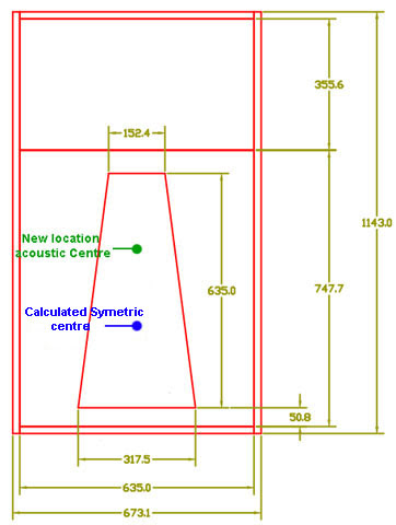
Acoustic centre of the mouth:
Usually we tend to position the acoustic centre to its symmetrical centre. That seems logical but from an acoustic point of view that is not correct. In an ideal world, like our models, the acoustic centre is the exact centre of a perfect circle. In reality we don’t have perfect circular mouth shapes for our subs. As long the mouth is more or less square shaped, the location of the acoustic centre is the same as the symmetrical centre. When the ratio between the longest and smallest side becomes larger than approximate 1.2 : 1, the acoustic centre of the mouth starts to shift enough to have influence on its ¼ WL behaviour. In case of the Keystone, its mouth is also under a 90 degree corner from the acoustic centre of the path and therefore creating a bend in the acoustic centre line. That means the correction we use for bends also needs to be implemented to find the correct acoustic centre of the Keystone’s mouth. Also its key form seems to shift the acoustic centre upwards. This is how the Key shape and Danley’s "V" throat are related. I believe Danley uses this "V" throat to change the high pressure zone towards the centre of the driver to improve loading of both sides of the driver (don’t mix those words with both sides of the cone) as discussed earlier in the Xoc1 design thread.
Mouth shape:
To be honest I don’t believe that shape/form of the mouth is of important influence on the response at frequencies that are much larger (till some degree of course). We know that our reflectors need to be 1/4WL in diameter to have a true influence on soundwaves. Therefore I don’t see any reason why we should treat the keystone mouth shape any different. In other words you can use any shape (within limits of extreme of course) as long the acoustic centre in the mouth stays at the same position and the total surface of mouth stays the same too.
The shape of the Keystone is stretched and the longest diameter is about 63,5cm ( = 0,635 metre).
343,64 (speed of sound) : 0,635 metre = 541,17 Hz
541,17 Hz : 4 (quarter wavelength) = 135,29 Hz.
In other words the lower limit of the influence of the Key-shape is approximate: 135Hz. Above it can have significant influence as the measurements of the Keystone already proved.
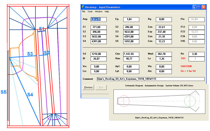
The volume change between driver and mouth:
About the increasing volume between driver and mouth: to model the extra volume between the driver and the mouth you need to change the "TH" of the Input Parameters page of HornResp, into "TH1". It does come with a concession. You will loose the extra input parameter between the driver and the virtual driver (= S3 in your model), in favour for the new parameter between driver and mouth.

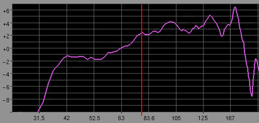
The unidentified peak around 74 Hz:
There is still one peak in the response I haven’t cleared up. This peak is located around 74Hz.in your measurements. It really is interesting if it is the result of the complexity of your design (unknown mystery perhaps?) or it is the result of an internal resonance of the frontal horn section. I mentioned earlier in posts about symmetrical designs and TH extenders that a large symmetric internal path can be used to create an extra peak in the response. If you design carefully, you might be able to position it around the efficiency dip between the efficiency peaks. It will help to lower dynamic power compression around this frequency at high levels. I am curious about other people thoughts about this 74 Hz area peak.
The errors in the new model:
My model is still far from perfect. My path length isn’t as accurate compared to the CAD skills of Oliver or Martin. The loss of the parameter between driver and virtual driver in favour to create the extra parameter between driver and mouth means you loose the correct expansion rate between the driver and the virtual driver. However in case of the Keystone this loss is acceptable since the expansion rate isn’t huge.
Right or wrong?
Although it may sound like a simple explanation I can't state I have build any Keystone yet to confirm my earlier statements. The biggest miss is a reliable Impedance plot to work with. Nevertheless, the Keystone mouth shape proved to be a very useful and practical tool to ‘tune’ the upper band by hand and ear until the best results are generated. Just be careful with the correct location of the true acoustic centre of the mouth because this is seems to be the key for the key-opening. Again, my model is still not perfect nor do I claim this model is correct. I just hope it helps clearing the 'mystery' around the Keystone or any designs that uses a 'different' mouth shape.
Just let me know what you guys think...
The model inputs:
(Thanks to TB46 since I used his drawings to go from)

As reply on your post#510 of the “TH-18 Flat to 35hz! (Xoc1’s design)” thread:
I must admit that the Keystone was some sort of mystery for me until I start analysing Danley’s "V" shape throat. The second 'ingredient' to improve the model for the Keystone is to implement the relative large increase of volume between the driver and the mouth since Hornresp calculates by Volume per location instead of using shapes.
Acoustic centre of the mouth:
Usually we tend to position the acoustic centre to its symmetrical centre. That seems logical but from an acoustic point of view that is not correct. In an ideal world, like our models, the acoustic centre is the exact centre of a perfect circle. In reality we don’t have perfect circular mouth shapes for our subs. As long the mouth is more or less square shaped, the location of the acoustic centre is the same as the symmetrical centre. When the ratio between the longest and smallest side becomes larger than approximate 1.2 : 1, the acoustic centre of the mouth starts to shift enough to have influence on its ¼ WL behaviour. In case of the Keystone, its mouth is also under a 90 degree corner from the acoustic centre of the path and therefore creating a bend in the acoustic centre line. That means the correction we use for bends also needs to be implemented to find the correct acoustic centre of the Keystone’s mouth. Also its key form seems to shift the acoustic centre upwards. This is how the Key shape and Danley’s "V" throat are related. I believe Danley uses this "V" throat to change the high pressure zone towards the centre of the driver to improve loading of both sides of the driver (don’t mix those words with both sides of the cone) as discussed earlier in the Xoc1 design thread.
Mouth shape:
To be honest I don’t believe that shape/form of the mouth is of important influence on the response at frequencies that are much larger (till some degree of course). We know that our reflectors need to be 1/4WL in diameter to have a true influence on soundwaves. Therefore I don’t see any reason why we should treat the keystone mouth shape any different. In other words you can use any shape (within limits of extreme of course) as long the acoustic centre in the mouth stays at the same position and the total surface of mouth stays the same too.
The shape of the Keystone is stretched and the longest diameter is about 63,5cm ( = 0,635 metre).
343,64 (speed of sound) : 0,635 metre = 541,17 Hz
541,17 Hz : 4 (quarter wavelength) = 135,29 Hz.
In other words the lower limit of the influence of the Key-shape is approximate: 135Hz. Above it can have significant influence as the measurements of the Keystone already proved.
The volume change between driver and mouth:
About the increasing volume between driver and mouth: to model the extra volume between the driver and the mouth you need to change the "TH" of the Input Parameters page of HornResp, into "TH1". It does come with a concession. You will loose the extra input parameter between the driver and the virtual driver (= S3 in your model), in favour for the new parameter between driver and mouth.
The unidentified peak around 74 Hz:
There is still one peak in the response I haven’t cleared up. This peak is located around 74Hz.in your measurements. It really is interesting if it is the result of the complexity of your design (unknown mystery perhaps?) or it is the result of an internal resonance of the frontal horn section. I mentioned earlier in posts about symmetrical designs and TH extenders that a large symmetric internal path can be used to create an extra peak in the response. If you design carefully, you might be able to position it around the efficiency dip between the efficiency peaks. It will help to lower dynamic power compression around this frequency at high levels. I am curious about other people thoughts about this 74 Hz area peak.
The errors in the new model:
My model is still far from perfect. My path length isn’t as accurate compared to the CAD skills of Oliver or Martin. The loss of the parameter between driver and virtual driver in favour to create the extra parameter between driver and mouth means you loose the correct expansion rate between the driver and the virtual driver. However in case of the Keystone this loss is acceptable since the expansion rate isn’t huge.
Right or wrong?
Although it may sound like a simple explanation I can't state I have build any Keystone yet to confirm my earlier statements. The biggest miss is a reliable Impedance plot to work with. Nevertheless, the Keystone mouth shape proved to be a very useful and practical tool to ‘tune’ the upper band by hand and ear until the best results are generated. Just be careful with the correct location of the true acoustic centre of the mouth because this is seems to be the key for the key-opening
. Again, my model is still not perfect nor do I claim this model is correct. I just hope it helps clearing the 'mystery' around the Keystone or any designs that uses a 'different' mouth shape.Just let me know what you guys think...
The model inputs:
(Thanks to TB46 since I used his drawings to go from)
Last edited:
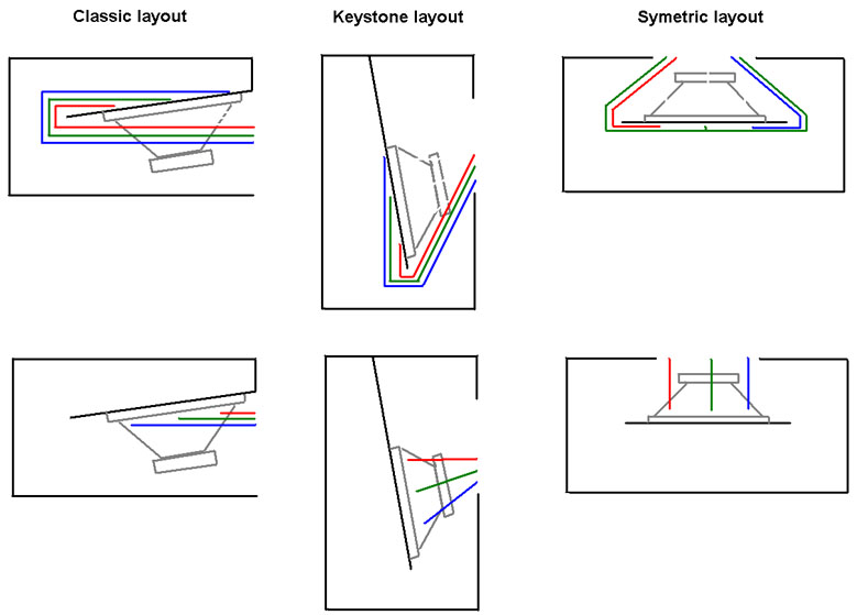
About the relation between the extra stability in excursion and the Keystone’s custom mouth shape.
I don’t think its special shape has real influence on that. What I do know is that there seems to be a relation between the distance variations from the cone to the mouth.In that way the keystone layout is improved over the "classic TH layout".
I tried to visualise that in a simplistic picture that represents the schematic views of the three different layouts: Classic, Keystone and Symmetric.
The colours represent different lengths from several positions of the cone towards the mouth. The Keystone does show an significant improvement over the "classical layout" (just on one side of the cone) but the symmetric layout is most optimised and at both sides of the cone. By introducing a narrowing throat in the symmetric layout you can improve it even further. At low power these difference don't seem to be significant but at high power the differences in forces become much larger.
Last edited:
Djim,The unidentified peak around 74 Hz:
There is still one peak in the response I haven’t cleared up. This peak is located around 74Hz.in your measurements. It really is interesting if it is the result of the complexity of your design (unknown mystery perhaps?) or it is the result of an internal resonance of the frontal horn section. I am curious about other people thoughts about this 74 Hz area peak.
Right or wrong?
Although it may sound like a simple explanation I can't state I have build any Keystone yet to confirm my earlier statements. The biggest miss is a reliable Impedance plot to work with. Nevertheless, the Keystone mouth shape proved to be a very useful and practical tool to ‘tune’ the upper band by hand and ear until the best results are generated. Just be careful with the correct location of the true acoustic centre of the mouth because this is seems to be the key for the key-opening
Some interesting reverse engineering and nice ways to fool Hornresp !
Your S4 distance appears to be a bit long, might be more representative of the actual cabinet if it pointed towards the area center of the Keystone exit rather than the narrow top part.
Because of the cone depth, the area at S2 actually gets a bit larger than shown in the sim, then reduces again at 20 cm from S2, for what its worth.
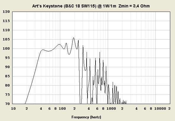
Your simulation shows a dip centered around 55 Hz that the real cabinet does not exhibit, but seems fairly close agreement with the upper peaks and dips as measured on the ground at two meters.
I chose two meters as a measurement distance because measurements at 10 meters are messed up by reflections from my pump house, unless I place the mic in the middle of the road, which requires a constant lookout for traffic.
Regarding the “unidentified peak around 74 Hz”, that could be a result of the dispersion characteristics of the Keystone cabinet or a bit of wind. Wish I had saved the response curve of the Keystone placed upside down, and on the side, the location of the dips and peaks were quite different and more ragged.
The interaction of the driver”s front and back radiation coupled with the Keystone exit shape causes some interesting directional behavior.
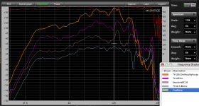
Posted below are measurements of the Keystone at various distances, most of the tests previously posted in this thread were done at 2 meters using an RTA 420 mic laying on a piece of plywood on the dirt.
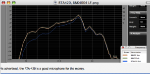
The RTA 420 mic response rolls off slightly below 60 Hz, about 1 dB down at 40 Hz, 2dB down at 30Hz, 4 dB down at 16 Hz. That falling response curve makes the Keystone measurements look a little more upward tilted than the actual response is.
The response using the B&K 4004 microphone (at an unknown distance) shows the response to be +/- 3 dB from 35 to 230 Hz, and inverts one of the upper peaks at around 180 Hz compared to the 2 meter tests.
Art
Attachments
Hi Art,
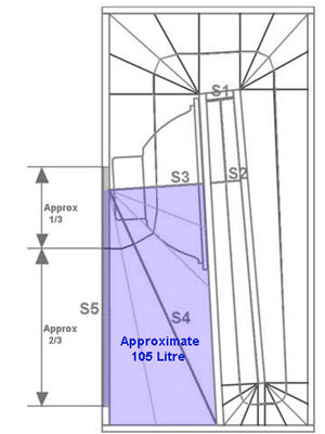
I agree Art, the distance between S3 and S5 should be drawn more accurately to get better data. You could also improve the model by calculating the volume between S3 and S5 (the volume of segment 3 and 4 independently) instead of using the usual length of S4. With the Schematic Diagram in HornResp you could check if the volumes of segment 3 and segment 4 are the same as the volumes of the corresponding segments of the real cab. Volume accuracy gives more accurate models than distance accuracy because of the shape errors that HornResp can’t 'see'. The acoustic centre should be ending at (or just above because of bending correction) 1/3 from top-line of the mouth, similar to my picture.
I made a new correction by changing the lengths S3-S4-S5 and correcting the Volume of Segments 3 and 4:
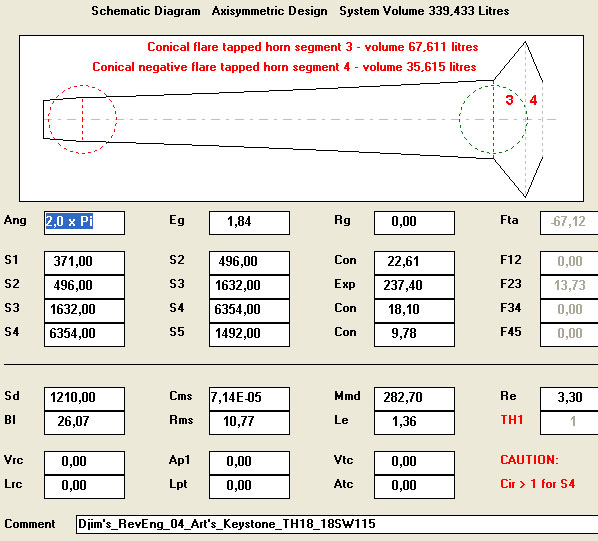
The Response of this new input page looks like this:
I agree Art, the distance between S3 and S5 should be drawn more accurately to get better data. You could also improve the model by calculating the volume between S3 and S5 (the volume of segment 3 and 4 independently) instead of using the usual length of S4. With the Schematic Diagram in HornResp you could check if the volumes of segment 3 and segment 4 are the same as the volumes of the corresponding segments of the real cab. Volume accuracy gives more accurate models than distance accuracy because of the shape errors that HornResp can’t 'see'. The acoustic centre should be ending at (or just above because of bending correction) 1/3 from top-line of the mouth, similar to my picture.
I made a new correction by changing the lengths S3-S4-S5 and correcting the Volume of Segments 3 and 4:
The Response of this new input page looks like this:
Last edited:
Hi Art,
The dip around 55Hz is the result of the usual modelling errors. The problem is the peak around 40Hz. In your measurement it is almost flat between 55 Hz down to 42 Hz (+/- ½ dB). If you compare with the Xoc1-TH18 for instance you see a similar error, the measurements rolls of earlier.
You can correct the cone volume like TB46 did (I'll use his inputs). If you do so, you also have to correct the pathlength since adding a value in ATC needs a correction in Horn Segment . You also need a correction for the raising inductance of the VC. In other words an inductance correction related to frequency.
Of course the Response you will get is only usable in the lowest part of the response to see what happens around the low corner. As you can see the bump at 40Hz is gone and also the dip at 55Hz, in a similar way like your measurement.
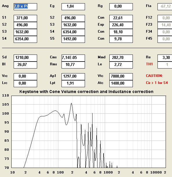
Last edited:
Hello Art,
I stumbled onto a thread on SoundForums that led me to this Keystone project. I'm still reading through the thread, but I think I'm going to take it on. I'm wondering what your current favored 18 is? I'm leaning toward the B&C 18TBW100, as I read (your post) that it's a good ceramic substitute for the 18SW115. Unless there's something else you recommend. Does the design dictate 4 or 8 ohm, or is that up to me? The largest amp I envision using would be the QSC PL380, which is 1250w @8, or 2500w@4.
This looks like a very straightforward build. How much time are people spending?
Although I built a house, I've never built a speaker cab. Are these cabs held together with super tough glue and trim nails, or is there more to it than that?
Thanks again for sharing this project!
Grant
Grant,
The B&C 18TBW100 would be a good lower cost alternative to the 18SW115.
In either case, I'd go with the 4 ohm version, 2500 watts is still not as much power as they will take. I bridge a Crest CA9 into each of mine, probably around 2-3K watts peak, and I'd like another 3 dB of power.
Langston Holland bridged a QSC PL380 (about 5K + peak) in to his 4 ohm DSL TH-118, and said that really got it going. Josh Ricci put around 10K into his B&C 21SW115 before tearing up the cone...
Although trim nails and glue are probably adequate, I always use screws and yellow glue (Tightbond II or Elmer's) for road cabinets with four horsepower kicking around inside. With as warped as the Aruca plywood I generally use is after making it from the tropics to the high desert, the screws (and a ton of clamps) help pull the wood back in line.
Build time varies with experience. I just built a tapped horn sub similar in size and complexity to the Keystone for my back yard, it took about 9 hours including applying wood filler, sanding, two coats of paint, stretching grill cloth, wiring and loading speakers.
Building a pair (or more) of speakers compared to one can save a little time per cabinet, but I'd figure estimating around 20 hours for a pair would be reasonable since you already have wood butcher skills but no speaker cabinet experience.
Art
oliver no drawings for the dual lab 12... how do u fit those in to the baffle...??Hi Art,
I added your comments in note form to the drawing, if you find anything else, or want to add anything let me know.
Regards,
Hi maxo,
The internal width was 25" (or so, depending on the wood thickness), and they should fit nicely side by side where the 18" is in the drawing.
Regards,
ic,
so if you look at the cab facing the mouth the drivers must be side to side or
one behind the other
Max.
Max,ic,
so if you look at the cab facing the mouth the drivers must be side to side or
one behind the other
Max.
I made an adapter plate to fit the two 12" over the existing hole cut for the 18".
Looking at the cabinet with the 45 inch dimension vertical, the two Lab 12" were mounted side by side horizontally.
I would recommend the B&C 18TBW100 over a pair of Lab 12, better performance and less $$ and weight.
Art
The Keystone design would commonly be referred to as a tapped horn.that bc driver looks great... hey the keystone what kind of design is and what are the diference with the bjorno 3015lf tqw sub published here...just wondering as they look similar inside
Bjorno is very giving with simulations, and has posted hundreds of designs, you would have to link me the one your question is about for me to say what the difference is.
After hearing the gross distortion the Eminence 4015LF had when driven near Xmax in the Keystone, I would not want to consider the lighter 3015LF for a low frequency, high power TH.
That said, harmonic distortion makes a speaker sound a lot louder than it is, many seem to enjoy it.
The Keystone design would commonly be referred to as a tapped horn.
Bjorno is very giving with simulations, and has posted hundreds of designs, you would have to link me the one your question is about for me to say what the difference is.
After hearing the gross distortion the Eminence 4015LF had when driven near Xmax in the Keystone, I would not want to consider the lighter 3015LF for a low frequency, high power TH.
That said, harmonic distortion makes a speaker sound a lot louder than it is, many seem to enjoy it.
this is the one
http://www.diyaudio.com/forums/subwoofers/185836-3015lf-th-35-40hz-but-only-20-deep-help.html
- Home
- Loudspeakers
- Subwoofers
- Keystone Sub Using 18, 15, & 12 Inch Speakers