Thank you Rademakers, and thank you Don Hills. You have made Cubos understandable. I have presented several designs and have always included
the HornResp input screen with the building plans. This allows people to modify the design or change the driver and sim the modifications. Not everyone
uses the inputs, not everyone cares. Rademakers use of comparative inside SPL/Freq plots is valid, just not my preference.
Thanks guys for your contributions to this forum, I have learned something!
Don
Last edited:
Cubo and Hornresp
Hi,
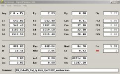
The other way to model the Cubo in Hornresp is to treat the chamber as a large throat chamber (Vtc/Atc), set S1 and S2 to the horn throat size, the other three sections can be used to define the horn and the driver location.
Regards,
Hi,
The other way to model the Cubo in Hornresp is to treat the chamber as a large throat chamber (Vtc/Atc), set S1 and S2 to the horn throat size, the other three sections can be used to define the horn and the driver location.
Regards,
Attachments
Hi,
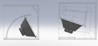
A while back a made a quick sketch of three different models of the Cubo15 (sorry, I don't recall where I found the original data). This is not a completed drawing, and should not be seen as such, just to show the different versions, and the general locations for the Hornresp data inputs.
Regards,
A while back a made a quick sketch of three different models of the Cubo15 (sorry, I don't recall where I found the original data). This is not a completed drawing, and should not be seen as such, just to show the different versions, and the general locations for the Hornresp data inputs.
Regards,
Attachments
The measurements (gain over 18") have been consistent in quite different rooms.as the room interactions would affect both cabinets
Your measurements also give more low end in the 40 Hz area as the HR sim, do they not? My tapped horns I build seem to keep closer to the HR sims then these "tapped reflexes". Perhaps it's super stitious but .for that reason I keep significant chamber sizes in my design
I did come to the same conclusion, pretty much in the same way. That method also allowed me to simulate Cubo Extended in Hornresp.close enough to be able to use Hornresp as a protoyping tool
I use this method mostly. Except I use different segment steps and arrive at a different chamber size (smaller). Regarding the pdf: That first Cubo design isn't mine, it looks more like a ARLS IIRC.The other way to model the Cubo in Hornresp is to treat the chamber as a large throat chamber (Vtc/Atc), set S1 and S2 to the horn throat size
I do think Cubo Extended is recommended.
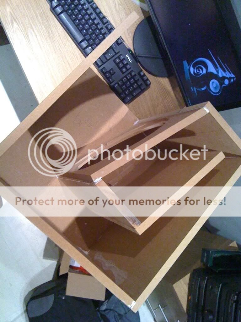
@Boscoe: Good luck with the build! Perhaps some pictures could be in order?
Best regards Johan
@Boscoe: Good luck with the build! Perhaps some pictures could be in order?
Best regards Johan
Yes by all means should be all done after in the new year!
Although the "simplified" Cubo model for Hornresp may not match the real thing exactly, it is still useful for testing different drivers for use in the design. Once you see the results for the recommended driver, you can see if an alternate driver will provide similar results. You can also use the Wizard to nudge some of the dimensions and see if changes to the geometry would improve the performance with the alternate driver.
The main thing that is usually missing from these models is the amount by which the driver volume changes the dimensions. This can be sigificant when the driver is placed in a narrow part of the horn, but is probably not a problem in Cubo where the driver is placed in either the "back chamber" or the "horn mouth", both of which are generously sized. To try it, work out the profile area (side view) of your chosen driver, then subtract it from either S2 or S4 as appropriate.
The main thing that is usually missing from these models is the amount by which the driver volume changes the dimensions. This can be sigificant when the driver is placed in a narrow part of the horn, but is probably not a problem in Cubo where the driver is placed in either the "back chamber" or the "horn mouth", both of which are generously sized. To try it, work out the profile area (side view) of your chosen driver, then subtract it from either S2 or S4 as appropriate.
Hi Don Hills,
I would recommend against subtracting the driver profile from S2 or S4 in Hornresp, it could alter the overall horn profile too much, e.g.: take a look at what that would do to the TH-Spud. I would disregard this in Hornresp, and use AkAbak for the more detailed analysis.
Regards,
Hi Boscoe,
I want to add the source for the original data used to generate the sketch in Post #23:
Home
There you'll also find a page on the Cubo12:
Cubo 12
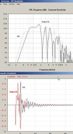
I'll attach an Hornresp SPL and Impulse comparison between the cubo-12 from that page, and a simple bass-reflex.
Regards,
I would recommend against subtracting the driver profile from S2 or S4 in Hornresp, it could alter the overall horn profile too much, e.g.: take a look at what that would do to the TH-Spud. I would disregard this in Hornresp, and use AkAbak for the more detailed analysis.
Regards,
Hi Boscoe,
I want to add the source for the original data used to generate the sketch in Post #23:
Home
There you'll also find a page on the Cubo12:
Cubo 12
I'll attach an Hornresp SPL and Impulse comparison between the cubo-12 from that page, and a simple bass-reflex.
Regards,
Attachments


I add 200 cm^2 (to 1500 cm^2) for the magnet inside the chamber, and take 200 cm^2 off (1500 cm^2) for the magnet inside the horn/port. This equals to 8 liters of difference in volume for the Vtc.This can be sigificant when the driver is placed in a narrow part of the horn, but is probably not a problem in Cubo where the driver is placed in either the "back chamber" or the "horn mouth", both of which are generously sized. To try it, work out the profile area (side view) of your chosen driver, then subtract it from either S2 or S4 as appropriate.
With the magnet inside the chamber for maximum output or with the magnet inside the horn for lowest extension respectively.
@Boscoe: Glad you like the result. Any plans for the finsih?
Best regards johan
I add 200 cm^2 (to 1500 cm^2) for the magnet inside the chamber, and take 200 cm^2 off (1500 cm^2) for the magnet inside the horn/port. This equals to 8 liters of difference in volume for the Vtc.
With the magnet inside the chamber for maximum output or with the magnet inside the horn for lowest extension respectively.
@Boscoe: Glad you like the result. Any plans for the finsih?
Best regards johan
Yes I would like to do a thick resistant matt black coating but don't really know how to go about it!
Can you get hold of Warnex? Two to three layers with a textured roller should do it. Oh, and if you haven't done it already, rounding the corners off with a rounding bit (radius 6 -9 mm/ 1/4"-3/8").
Best regards Johan
Okay thanks and yep I will be rounding off the corners.
The difference between the Cubo design and a conventional TH is comparable to the difference between a conventional front loaded horn, and a bandpass horn.
The bandpass horn and the cubo have a compression chamber that allows a lower frequency response with a shorter horn path length.
The bandpass horn and the cubo have a compression chamber that allows a lower frequency response with a shorter horn path length.
Attachments
- Status
- This old topic is closed. If you want to reopen this topic, contact a moderator using the "Report Post" button.
- Home
- Loudspeakers
- Subwoofers
- Cube horn design?