Pyros yes this box will do a lot more damage than the one you built. When you are pumping 3kw through a powerful driver stuff is bound to vibrate!
I'm not going to be running that much power but hey ya never know What the future brings. Might as well build up the box right the first time!!
I'm not going to be running that much power but hey ya never know What the future brings. Might as well build up the box right the first time!!
To be honest I think those 2x13mm can have more effect (positive or negative) to the LF response then all corner bracing together...
I,m having a go at putting together an AkAbak script to sim the extra area near the mouth. I,ve got the script to work with a couple of extra sections, one being a negative taper, - just need to punch in the numbers

Maybe tomorrow..... I,m too tired now!
Regards
Martin
Ya just woundering if I should put in extra bracing befor I seal up my boxs. AndyPyros yes this box will do a lot more damage than the one you built. When you are pumping 3kw through a powerful driver stuff is bound to vibrate!
I'm not going to be running that much power but hey ya never know What the future brings. Might as well build up the box right the first time!!
Akabak Analysis TH18
Hi
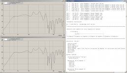
Results of 6 segment sim in akakak adding the extra area unaccounted for in the hornresp sim. As discussed in posts 292 & 293
The screengrab shows the data used and the resultant sim labelled TH18PDM
The TH18PD graph shows the 4 segment sim as exported from Hornresp - with the path length adjusted to take account of adding all the corner reflectors.
Driver is still the PD1850 but results are presented for comparison of the response curves.
The rest of the horn is as linear as I could acheive, with no great descrepancies from the horn taper.
Overall the result is a slightly smoother response - half a dB down at 45hz
and 1 dB up at 30Hz.
I suppose this is the effect that might be expected by adding a small bandpass chamber.
Regards
Martin
Hi
Results of 6 segment sim in akakak adding the extra area unaccounted for in the hornresp sim. As discussed in posts 292 & 293
The screengrab shows the data used and the resultant sim labelled TH18PDM
The TH18PD graph shows the 4 segment sim as exported from Hornresp - with the path length adjusted to take account of adding all the corner reflectors.
Driver is still the PD1850 but results are presented for comparison of the response curves.
The rest of the horn is as linear as I could acheive, with no great descrepancies from the horn taper.
Overall the result is a slightly smoother response - half a dB down at 45hz
and 1 dB up at 30Hz.
I suppose this is the effect that might be expected by adding a small bandpass chamber.
Regards
Martin
Attachments
I think you are right there. It's only a pity Akabak doesn't have the ability to show how the design would be influenced when the driver is loaded with max power. Nice work again MartinHi
Results of 6 segment sim in akakak adding the extra area unaccounted for in the hornresp sim. As discussed in posts 292 & 293
The screengrab shows the data used and the resultant sim labelled TH18PDM
The TH18PD graph shows the 4 segment sim as exported from Hornresp - with the path length adjusted to take account of adding all the corner reflectors.
Driver is still the PD1850 but results are presented for comparison of the response curves.
The rest of the horn is as linear as I could acheive, with no great descrepancies from the horn taper.
Overall the result is a slightly smoother response - half a dB down at 45hz
and 1 dB up at 30Hz.
I suppose this is the effect that might be expected by adding a small bandpass chamber.
Regards
Martin

Hi Djk, HornResp also models excursion but the reality shows something different (and I don't mean pwr compr)."It's only a pity Akabak doesn't have the ability to show how the design would be influenced when the driver is loaded with max power" What do you mean? AkAbak models excursion.
I’ll try to make it more concrete for you. If you build a TH design based on a sim you will see that the LF output differs from the prediction. I don’t mean the overall SPL differences (these can be explained) but specific differences in the LF part of the band pass. Often this results in less SPL at Fb (1/3WL) in return for less steep roll-off. I know the problem looks similar to Martin findings in post # 304 which is why I mentioned it. However, the models we used were optimised like Martin did but we still face the same 'problem' in reality every time again. I don't think HornResp or Akabak can model that.
But we made another observation. When you power the thing on more serious levels (3.2kW) you see the usual LF SPL drop below 2/3WL as part of power compression. However, it also looks like Fb is starting to drop in frequency a little. If we use different drivers with half AES power ratings we didn’t see this 'drop'. No we are trying to figure out if it is related to:
1.) Specific drivers (problem - we only have one type that can handle such power)
2.) Some kind of logarithmic type of rising in absorption vs power trough panel flexes (this looks the most likely to me).
3.) If it is possible it has something to do with the changing of air mass by the higher pressure.
And I don't think you can model that either in Akabak") Anyway, what sounds more logical to you Djk, or have you other ideas?
Anyway, what sounds more logical to you Djk, or have you other ideas?
But we made another observation. When you power the thing on more serious levels (3.2kW) you see the usual LF SPL drop below 2/3WL as part of power compression. However, it also looks like Fb is starting to drop in frequency a little. If we use different drivers with half AES power ratings we didn’t see this 'drop'. No we are trying to figure out if it is related to:
1.) Specific drivers (problem - we only have one type that can handle such power)
2.) Some kind of logarithmic type of rising in absorption vs power trough panel flexes (this looks the most likely to me).
3.) If it is possible it has something to do with the changing of air mass by the higher pressure.
And I don't think you can model that either in Akabak
Anyway, what sounds more logical to you Djk, or have you other ideas?
Last edited:
40Hz horns with $700 usd drivers? If 40Hz is all you are after why not stick with more of the efficient SS15's, but use better/more cost effective drivers?
If 140dB & 30Hz extension is the goal I think you will need 4 cabinets of a different design.
Why is there no model of the 18sound driver?
Also why are the sections set to conic, that should be parabolic right?
If 140dB & 30Hz extension is the goal I think you will need 4 cabinets of a different design.
Why is there no model of the 18sound driver?
Also why are the sections set to conic, that should be parabolic right?
Ya just woundering if I should put in extra bracing befor I seal up my boxs. Andy
Did you end up using 3/4" outer panels? I built 2 SS15 enclosures (w/3015LF drivers) and the panels vibrate just a bit. Next time I'll use 3/4" outside panels with the same/similar standard braces.
I used 3/4" throughout. The rear vibrats some. AndyDid you end up using 3/4" outer panels?
The 18lw2400 is on sale for 330 shipped. I'll go with two of those each in a TH18 box braced very well made with good ply and I'll use the xti4000 to power. I'll see how that works for me for the time being.
I only see the 8 ohm version listed on the site but on 18sound's site they list a 4 and 8 ohm version. I'll call them and see Whst they say.
I wonder how the 18LW2400 driver would compare to the RCF LF18N451 in the real world.
Note: Both drivers are at (xmax + 1.6mm) and are being modeled in Xoc1's TH18
Attachments
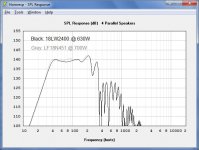
So the 18lw2400 is theoretically hitting xmax with only 630 watt input, yet it was mentioned before that they need at LEAST 1500 watts to get anywhere near xmax?
Either way i just grabbed the xti4000 last night so I have some power to play around with. Now I need to get the drivers and some wood! yayy!
Either way i just grabbed the xti4000 last night so I have some power to play around with. Now I need to get the drivers and some wood! yayy!
40Hz horns with $700 usd drivers? If 40Hz is all you are after why not stick with more of the efficient SS15's, but use better/more cost effective drivers?
If 140dB & 30Hz extension is the goal I think you will need 4 cabinets of a different design.
Why is there no model of the 18sound driver?
Also why are the sections set to conic, that should be parabolic right?
Are you directing this towards me dan? I am doing it because I do want that extra 10hz that the ss15 doesn't have.
I'm currently building another ss15 for a friend, i can test that with some power but i doubt it will have the output i'm looking for! Also, are you saying 4 of xo1c's cabs won't hit the 140db @ 30hz?
and yes can someone please model those 18 sound drivers. the 2400 and the 9600c.
i didn't do the math(djim is better @ itSo the 18lw2400 is theoretically hitting xmax with only 630 watt input, yet it was mentioned before that they need at LEAST 1500 watts to get anywhere near xmax?
Either way i just grabbed the xti4000 last night so I have some power to play around with. Now I need to get the drivers and some wood! yayy!
)but first you got powercompression.
second hr only shows sine waves excursion,so in real live use excursion wil be much less.
so you might need that 1500 watts to get to x-max in real live use
.
Last edited:
Okay so the modeling is just showing xmax using sin waves not program power..got it!i didn't do the math(djim is better @ it)
but first you got powercompression.
second hr only shows sine waves,so in rael live use excursion wil be much less.
so you might need that 1500 watts to get to x-max in real live use.
Dan, Xoc1’s design is based on Jbell’s SS15 which is the best price versus efficiency. The goal was to keep the efficiency but extend its range to be able to play all types of music (including dance and D&B). The -3dB point at 38Hz (1/3WL) is therefore a very good balance between efficiency and frequency extension. Maybe not your cup of thee but that’s personal.40Hz horns with $700 usd drivers? If 40Hz is all you are after why not stick with more of the efficient SS15's, but use better/more cost effective drivers? If 140dB & 30Hz extension is the goal I think you will need 4 cabinets of a different design.
Why is there no model of the 18sound driver? Also why are the sections set to conic, that should be parabolic right?
The idea of using the expensive 9600c was just to show the max potential of the design. For the price of one 9600c you can buy two 2400’s which I would choose. Also this design is very easy on drivers and you can fill it with many different types of 18"s and even 15"s if you like.
For both drivers there is something to say so it really depends on what is more important to you.I wonder how the 18LW2400 driver would compare to the RCF LF18N451 in the real world. Note: Both drivers are at (xmax + 1.6mm) and are being modeled in Xoc1's TH18
Still a little uncomfortable with the idea, I can see. It is actually quiet simple. TH’s have about 5dB more efficiency over basreflex. So if basreflex has 128dB max the TH would end at 133dB, right? Well, how would that be possible if the excursion isn’t similar to basreflex? If excursion was higher in TH’s you would never reach the +5dB at max power and it would make no sense using TH’s in the first place. Like basreflex if you drop the system Fb below the Fs of the driver you will see the excursion rapidly increases.i didn't do the math(djim is better @ it but first you got powercompression. second hr only shows sine waves excursion,so in real live use excursion wil be much less. so you might need that 1500 watts to get to x-max in real live use.
Clean single sine waves always show higher excursion and do radiate better to air. That’s why bass sounds often have strong sine waves in them. If the Fb of an TH design is set higher than the Fs of the driver you can use AES power ratings as given in the Thiele-Small parameters of the driver.Okay so the modeling is just showing xmax using sin waves not program power..got it!
Last edited:
The reason why I posted up my design in the first place was Crescendos request for a cabinet that would sim to 4 cabs @ 140db @ 35hz (and was more compact than the 30Hz monsters that we were discussing) I showed this sim with the PD 1850 in post 215are you saying 4 of xo1c's cabs won't hit the 140db @ 30hz
The PD 1850 might not be as efficient as most, but it plays a bit lower than most drivers. In theory it needs more power, but it also has low thermal compression levels
40Hz horns with $700 usd drivers? If 40Hz is all you are after why not stick with more of the efficient SS15's, but use better/more cost effective drivers?
Look at the comparison using a 3015lf in post 218
The ss15 can not use an 18" driver. A decent 18" driver will shift more air than a 15". The bigger cab sims about 10hz lower - take your choice - there is always a compromise somewhere.
If your are refering to what I simmed with akabak then I had to set hornresp to Con to export the data. If there is a better setting I could use, then please tell!why are the sections set to conic, that should be parabolic right?
Anyone up to compare the compression levels of the LF18N451 http://www.parts-express.com/pe/showdetl.cfm?Partnumber=294-894# vs 18LW2400 http://www.loudspeakersplus.com/pdfs/18LW2400.pdf? As they seem to be the best options (bang for buck) on this side of the sea. I guess we would just need the comp levels of the RCF driver since the 18Sound levels have been calculated earlier in this post.
And if a driver could take more power than the sim displays to reach xmax, then will it play louder or is the thermal/mechanical compression making it more difficult for the driver to reach xmax, therefore taking more real-world power to reach it's sim'd output at the hornresp xmax?
And if a driver could take more power than the sim displays to reach xmax, then will it play louder or is the thermal/mechanical compression making it more difficult for the driver to reach xmax, therefore taking more real-world power to reach it's sim'd output at the hornresp xmax?
Last edited:
- Home
- Loudspeakers
- Subwoofers
- C/E/X PA Flat to 30 (FT30) PA TH Awesomeness