Hi,
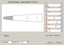
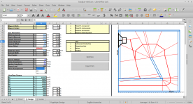
i'm about to build a mltqwt, see first attachment. As there is no boxplan for that,
i'd like to ask what the current proven formula is for a 180° turn/fold.
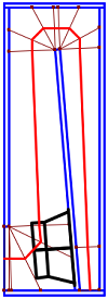
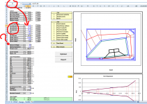
The geometrically closest boxplan is maybe the BOXPLAN-SFTH, see second attachment.
As far as i understand, in this case it's all about how long the panel in the middle
shoud be, as the taper dictates the angle of the panel, and this panel therefor would hit in the middle of the top-panel(if it were made long enough). Is this a correct assumption?
Thanks for any help.
i'm about to build a mltqwt, see first attachment. As there is no boxplan for that,
i'd like to ask what the current proven formula is for a 180° turn/fold.
The geometrically closest boxplan is maybe the BOXPLAN-SFTH, see second attachment.
As far as i understand, in this case it's all about how long the panel in the middle
shoud be, as the taper dictates the angle of the panel, and this panel therefor would hit in the middle of the top-panel(if it were made long enough). Is this a correct assumption?
Thanks for any help.
Attachments
I think the nice thing about the box plans (if they do this)is the driver and line lengths and reality vs simmed dimensions . A 90 degree turn and a 180 degree turn incorporated in a taper or CSA change at that point, or a diver entry etc, are misrepresented often in simulated inputs chosen vs built in wood.
A magnet sticking 2” out the exit of a taped horn is possible if a turn 90 degrees is in that exit. But if endfired that driver will never even go in to be mounted.
Your turn is interesting and placing the length from the end of the box, and equal distances from the sides it’s splitting will make that easy to decide. Because if you look at the CSA as you round both corners the issues of concern is no longer a concern. Each fold in a box or rectangle has more going on in the corners than shifting the panel up or down as a taper or expansion accuracy might make you want to think out.
The corners trap standing waves so we don’t mind. But on that note, realize the constant CSA is distrupted a lot briefly and in two spots for a 180... but it’s not an issue If it’s helping other issues.
Last edited:
Coming soon... FLHs...
I've managed to solve two issues that were preventing me from moving forward with a BOXPLAN for a FLH: (1) calculating the volume of an irregular chamber, and (2) optimizing the size of 45 degree corner "reflectors" (for those of you who still want to use them in bass horns).
I've managed to solve two issues that were preventing me from moving forward with a BOXPLAN for a FLH: (1) calculating the volume of an irregular chamber, and (2) optimizing the size of 45 degree corner "reflectors" (for those of you who still want to use them in bass horns).
Attachments
Coming soon... FLHs...
I've managed to solve two issues that were preventing me from moving forward with a BOXPLAN for a FLH: (1) calculating the volume of an irregular chamber, and (2) optimizing the size of 45 degree corner "reflectors" (for those of you who still want to use them in bass horns).
Oh this guy does. Nothing I have built can keep up to a proper FLH!
Oh this guy does. Nothing I have built can keep up to a proper FLH!
Word! I see you Brian with the vented chamber!
Technically, it's no longer a FLH.
FLH = BP4 with positive flare port.
Vented FLH = BP6.
Word! I see you Brian with the vented chamber!
Technically, it's no longer a FLH.
FLH = BP4 with positive flare port.
Vented FLH = BP6.
I'm going to make venting the chamber an option in this workbook.
Hi Brian,
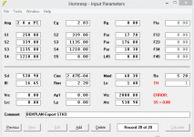
it seems like the BOXPLAN-MLTL3 does not calculate the length of L12 correctly, if the driver is offset. See the attached.
That layout can't be mapped to a Hornresp model. That's why the BOXPLAN workbook is displaying a red "ERROR!" below the entry fields.
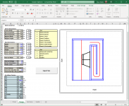
Hi Brian, I'm still playing around with the SHINSON boxplan Beta that was just released. I'm getting confused because the Box Parameters cells B11, B12, and B13 say h, w, h instead of one of them being the depth. It looks like cell D11 is supposed to be the depth, since the named range/cell window shows D next to the formula bar. I'm trying to model the Dayton PN395 15" woofer in a smallish box, and I thought I had a 24" wide x 32 inch deep box per the diagram. I think I'm actually modeling a 16" wide x 32" deep box that's 24" tall? Can you please help clarify / help me understand? Thanks!
Attachments
Hi Brian, I'm still playing around with the SHINSON boxplan Beta that was just released. I'm getting confused because the Box Parameters cells B11, B12, and B13 say h, w, h instead of one of them being the depth. It looks like cell D11 is supposed to be the depth, since the named range/cell window shows D next to the formula bar.
So, two things:
1. The diagram is a top-down cross-sectional view of the box. So the labels in the diagram are correct. This is why when you change "h (external)", there's no visible change to the diagram of the horn
2. In trying to fix that workbook, I came across a massive bug. The actual height of the horn was not being calculated correctly. I've done a quick update to the workbook that corrects that (the "w (internal)" field is now correctly displayed as "h (internal)", and calculated using the external height of the horn, minus panel thickness).
I've uploaded the corrected version of the workbook to my site - 0.5 Beta
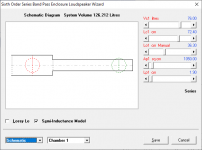
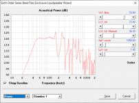
So here's another BOXPLAN workbook for a 6th order series-tuned bandpass alignment - one that should be pretty easy to build.
I actually put it together for two reasons:
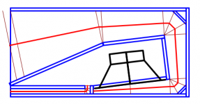
1. To prove a point - that a TH is basically a series-tuned 6th order BP alignment taken to its logical limit, one with significant out of band noise however because the layout doesn't help to reduce those effects.
2. To model the effects of "dogfood duct" type modifications to sim(this will be added in subsequent iterations of the workbook, but for now can be done via changing Ap2 in the resulting Hornresp sim.
Anyway, the workbook is available from my site, and it should be considered a BETA version for sure - let me know if you find any bugs")
This is also one of the few workbooks I have that doesn't require an optimization routine. Simply put in the chosen box dimensions, enter the chosen value for Ap1 (the csa of the external vent) and select the driver that you want to use from the Hornresp driver database (or enter the values yourself). Then export the sim to Hornresp to see what the results would look like.
Make sure that the generated image of the box's cross-section in the graph looks like something that can actually be built! I haven't added any error routines to the workbook yet to flag any physical build issues.
NOTE: There is a bug that I picked up in the Hornresp import routine. I'm not sure if it's because of the workbook or Hornresp itself, but it seems Hornresp will not accept values for Ap1 that are larger than 999.9 cm^2.
The eagle-eyed ones among you would notice that this particular fold looks like a stepped version of a certain popular TH created by one of the regulars here, if you move the mouth from the bottom of the image to the left side ...
I actually put it together for two reasons:
1. To prove a point - that a TH is basically a series-tuned 6th order BP alignment taken to its logical limit, one with significant out of band noise however because the layout doesn't help to reduce those effects.
2. To model the effects of "dogfood duct" type modifications to sim(this will be added in subsequent iterations of the workbook, but for now can be done via changing Ap2 in the resulting Hornresp sim.
Anyway, the workbook is available from my site, and it should be considered a BETA version for sure - let me know if you find any bugs
This is also one of the few workbooks I have that doesn't require an optimization routine. Simply put in the chosen box dimensions, enter the chosen value for Ap1 (the csa of the external vent) and select the driver that you want to use from the Hornresp driver database (or enter the values yourself). Then export the sim to Hornresp to see what the results would look like.
Make sure that the generated image of the box's cross-section in the graph looks like something that can actually be built! I haven't added any error routines to the workbook yet to flag any physical build issues.
NOTE: There is a bug that I picked up in the Hornresp import routine. I'm not sure if it's because of the workbook or Hornresp itself, but it seems Hornresp will not accept values for Ap1 that are larger than 999.9 cm^2.
The eagle-eyed ones among you would notice that this particular fold looks like a stepped version of a certain popular TH created by one of the regulars here, if you move the mouth from the bottom of the image to the left side
...Attachments
Last edited:
- Home
- Loudspeakers
- Subwoofers
- Spreadsheet for Folded Horn Layouts...