I would like to ask if it is possible to use any of the sheets to design TL in the style of PMC TB2?

Not at the moment.
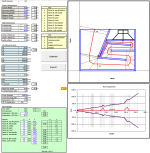
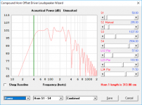
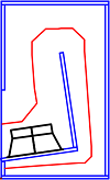
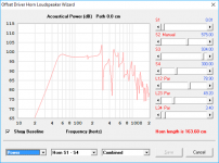
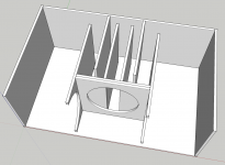
An offset rear-loaded horn...
This was an attempt to deal with the "notch" in the rear-loaded horn's response by offsetting the driver a bit. Obviously it's failed (at least this particular configuration), but maybe I can re-jig this workbook to do something else. Any FLHs that have a similar folding pattern?
This was an attempt to deal with the "notch" in the rear-loaded horn's response by offsetting the driver a bit. Obviously it's failed (at least this particular configuration), but maybe I can re-jig this workbook to do something else. Any FLHs that have a similar folding pattern?
Attachments
Generally when I design a back-loaded horn I make the cabinet about 45 to 48 inches high. This allows a tweeter placement close to 38 to 39 inches. I have measured a lot of people and this seems to be a good average height for tweeter placement.
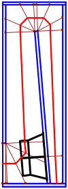
All this information will tell you that most back-loaded horns that I design end up being about three folds. With a compression chamber That is designed before the horn throat.
Hope that helps a little. The general shape is a rectangle with a 3.5:1 height versus depth ratio. Usually about 16 to 20 inches deep. This will allow a system Fs of around 25 to 35 hertz. If you go big, you might as well aim low right!
Generally when I design a back-loaded horn I make the cabinet about 45 to 48 inches high.
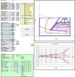
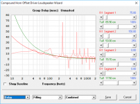
It looks like for an RLH, you've gotta go big or go home. I increased the height to 48 inches, and the "notch" in the sim is now about 3dB (once the region from S1 to just past the driver is properly damped). Fb is around 38 Hz though, which seems to work well for this particular driver (a 15" PA driver).
I can see though why these things (bass RLHs) are referred to music producers rather than music reproducers. The GD between 70 Hz to about 150 Hz is not the best.
What purpose does the compression chamber in a RLH really serve? Most of the RLH layouts I've seen have the throat at one end of the compression chamber, rather than the center, which means that the offset of the driver in the compression chamber isn't taken into consideration in the sim. I was therefore trying to avoid using one.
Attachments
This is basically acting as a capacitor in a crossover for a woofer. It's a low pass filter done mechanically. It has a large benefit if done correctly in keeping out the midrange coming out of the horn mouth. Group delay is a bit over stated in it's audibility. Actually a lot over stated in it's audibility. In normal music program material it is pretty much not noticeable. I have built very long front loaded horns that exhibited large group delay and it was never noticeable in actual use. It was measurable but not audible.What purpose does the compression chamber in a RLH really serve? Most of the RLH layouts I've seen have the throat at one end of the compression chamber, rather than the center, which means that the offset of the driver in the compression chamber isn't taken into consideration in the sim. I was therefore trying to avoid using one.
Last edited:
I have built very long front loaded horns that exhibited large group delay and it was never noticeable in actual use. It was measurable but not audible.
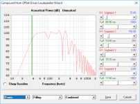
With FLHs, the situation is a bit different - all of the output is from the horn. With the RLH, there's output from both the horn and the driver. I tend to look at the change in GD over the passband, to get an idea of what impact it might have. The GD for this RLH rises to almost 20ms at around 115 Hz, before it drops back down to below 10ms at 65 Hz, and then rises back up again.
With FLHs, the situation is a bit different - all of the output is from the horn. With the RLH, there's output from both the horn and the driver. I tend to look at the change in GD over the passband, to get an idea of what impact it might have. The GD for this RLH rises to almost 20ms at around 115 Hz, before it drops back down to below 10ms at 65 Hz, and then rises back up again.
You are correct.
And even greater group delay is not audible with actual program material being played.
There are audibility tests. And there are actual listening tests. Many times the two are getting confused with one another. I have one very long front loaded horn that can have up to 88milliseconds of group delay. At the first public audition of this enclosure I had a great chat with a guy who became a good friend who wrote his paper on the audibility of group delay. And we looked at the simulations and then listened to various program material. No one could pin point anything in any listening test they did.
Every driver and enclosure has a degree of group delay. It seems to me that it is a number that is a little to high in the do not do list of people designing their enclosures. Vented enclosures are very easily more problematic. Passive radiator systems are definitely audible in my listening experience.
Anyway. I'm digressing.
This work you are doing is very considerate and well thought out Brian. And I'd like to thank you for your project.
I've added two more workbooks to assist with the design of simple THs for HT use (the resulting boxes tend to be tall, but occupy smaller floor-space, and are best used for TH designs that dig pretty low). Both workbooks should be considered "beta"... ")
Attachments

3.5
Still hoping for front loaded horn one day!
Well, I did one workbook that covers W-Bins...
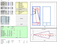
Another addition to the list - a workbook that can be used to design mass-loaded tapered quarter-wave tubes (TWQTs). I've found that this particular layout works well for getting the driver in the correct offset location to null out the first resonance.
Attachments
- Home
- Loudspeakers
- Subwoofers
- Spreadsheet for Folded Horn Layouts...