Hi all, new to the forums, but from what i've read you guys all really know your stuff, so I'd value your input on my design for a PA subwoofer for my band to use.
I am currently using this driver and amp combo in a sealed box as part of my home built jukebox, but as a PA sub for band use, it just doesn't cut it. Since money is quite tight at the moment due to an impending wedding, I have to use the driver and amp I've already got, despite their obvious unsuitability for the task being asked of them.
The TS specs given are specified as being with the 4 ohm voice coils wired in parallel, giving a 2 ohm load, but the amp is not two ohm stable, and I have a 600 watt (bridged into 8 ohm) amp I might want to use instead. If I wire the voice coils in series to get an 8 ohm load, will this alter the TS specs in such a way that my design is no longer tuned the way I want??
WinISD gives me a graph that shows a peak of 3.6dB around the 30Hz mark, and the -3dB point is about 24Hz. If you think I should be aiming for a different graph, let me know. In fact, i'd appreciate ANY suggestions or comments on the design or how I could improve it, bearing in mind I'm stuck with the driver and amp(s) I have.
Also if any more information would help, just ask!
Cabinet - 18mm MDF
Internal Dimensions - 700x700x450
Box Volume (Unadjusted) - 220 Litres
Driver Volume - 4.25 Litres
Plate Amp - 1.7 Litres
Port Volume - 4.2 Litres
Bracing Volume - 7 Litres
Box Volume (Adjusted) - 203.35 Litres
Ports - Two ports, 102mm inside dia.
Port Length - 220mm
Tuning Frequency - 28.57Hz
Driver - Response 300 Watt RMS Dual Voice Coil 12" Subwoofer
Dc Resistance: 1.7 ohms
Vas: 79.454L
Qms: 3.238
Qes: 0.446
Qts: 0.392
Sensitivity: 88.192 dB @ 1 watt & 1 metre
BL: 9.992TM
Fo: 28.77Hz
Sd: 514.72 sq cm
Plate Amp - 350 Watt RMS into 4 ohms
Thanks in advance!
A horn will be usable.
Throat area = 250cm
Mouth area = 3000cm
Length = 250cm
Rear volume = 15L
290L net volume, probably about 360L gross. This might be around 2' x 2' x 3' (external).
Average is about 100dB/W/1M in 2Pi (on the floor), 42hz~120hz (will need about 3dB of cut around 110hz).
Throat area = 250cm
Mouth area = 3000cm
Length = 250cm
Rear volume = 15L
290L net volume, probably about 360L gross. This might be around 2' x 2' x 3' (external).
Average is about 100dB/W/1M in 2Pi (on the floor), 42hz~120hz (will need about 3dB of cut around 110hz).
Thanks for the response. My experience has only ever been with sealed and traditional ported enclosures for auto and home theatre use. I'm doing as much reading as possible at the moment to try and get my head around tapped horns, since I think it would be the ideal thing for me.
The designs I have seen mostly look complicated, but would I be right in saying that you basically start with a horn throat thats about a quarter of Sd, and fold the horn around so that the rear of the driver is 'tapped' into the horn quite close to the mouth? Also that the horn mouth should be about twice the driver Sd.
I am having trouble working out how you work out the length of the horn, though... Any help would be greatly appreciated.
"I am having trouble working out how you work out the length of the horn, though... Any help would be greatly appreciated. "
Use McBean's Hornresp program. A horn must be a minimum of 1/4 wavelength of the lowest frequency you want to reproduce.
The driver you have will not do the job you want it to in a tapped horn (otherwise I would have suggested same). It would be fine for a home theater subwoofer tuned for 20hz or so, but not for PA.
..I am having trouble working out how you work out the length of the horn, though... Any help would be greatly appreciated..
Hi shaggerz,
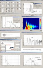
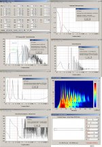
Played with your DVC driver where the coils are connected in series:
b
")
Attachments
Thanks but those pictures are too small to read
Read GM's hint on how to enlarge=
 the thumbnails : post #15 and #16:
 http://www.diyaudio.com/forums/subw...ndation-please-tb-w8-740-a-2.html#post2235651
b
It is as I suspected, the traditional horn is better suited for the parameters of this driver, yielding about 5dB more output overall, and better bandwidth too.
I would be in favor of a tapped horn, if I could use a different diver.
(bearing in mind I'm stuck with the driver and amp(s) I have.)
I would be in favor of a tapped horn, if I could use a different diver.
(bearing in mind I'm stuck with the driver and amp(s) I have.)
Thanks all... did not notice the 'enlarge' button down there
I see what you mean about the traditional horn yielding a better result. I have spent a few hours reading up on offset driver horns , and I think I am getting the hang of it, but will need to spend some more time.
My aim is to have the response reasonably flat between 30Hz and 100Hz. What happens above that doesn't interest me because I will be using both low and high pass filters to keep the input between 30Hz and 100Hz approximately.
While I have read three or four different versions of horn design tutorials, I'm not sure where some of the numbers come from. I am running late for work at the moment but will post more n00b questions a bit later.
Thanks to all for your help so far
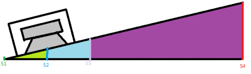
OK I am having a little trouble with the OD horn design I hope to use. Have attached a diagram of my understanding of it.
S1 = The cross sectional area at the "dead end" of the horn. If these two surfaces mate with no flat bit at the end, this will be zero.
S2 = The cross sectional area at the centre point of the driver.
S3 = ??? This one I don't quite get... How do you know how far along the horn this is?? I remember reading somewhere it should be the same distance from the centre line of the driver to S1 as it is from the centre line of the driver to S2. Is this correct? Does S2 even matter if the flare angle is constant the whole length of the horn? If the flare angle is constant, can there be only S1 (start of horn) S2 (area at centre line of driver) and S3 (area at horn mouth)?
S4 = The cross sectional area at the mouth of the horn.
L12 = Distance from S1 to S2
L23 = Distance from S2 to S3
L34 = Distance from S3 to S4
Do I understand correctly??
In deciding the size of S2, is it right that I should aim for an area that is approximately a quarter of the driver Sd? (And tweak in hornresp for best spl graph)??
Attachments
bjorno: looking through your screenshots there, I see a ton of the TS specs are different. I gather this is because you adapted them for voice coils in series rather than in parallel. Could you explain how you arrived at each of those numbers?
I also see some numbers pertaining to throat chamber... where does the throat chamber fit into the diagram I posted above?
I also see some numbers pertaining to throat chamber... where does the throat chamber fit into the diagram I posted above?
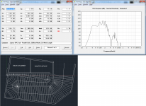
OK I think I have sort of gotten my head around this. After a few attempts at coming up with a design that's small enough for me to be happy to have it in my house, I've arrived at this.
Since I'm no expert, and its going to take a lot of time and sheet material, I would really appreciate some scrutiny of this design... I know its not perfect, but as long as I can confirm it will work as predicted, I will start building it.
Frequency response is essentially flat between 40 and 90Hz, output SPL is reasonably high and excursion can be kept to a minimum within that frequency range. I'll be implementing a 40Hz high pass filter for use with this unit.
Have attached a screenshot with the details and the Autocad 2011 DWG file. Please note I have somewhere between very few and zero CAD skills, so the drawing is very very rough and a lot of it is just eyeballed. Despite that, I'm hoping its accurate enough to get a reliable result when constructed.
Thanks in advance!
Attachments
Here are the details in plain text in case that is useful:
External Dimensions - 1159x747x636
Construction - 18mm MDF
S1 - 150cm2
S2 - 150cm2
S3 - 2200cm2
L12 - 178cm
L23 - 270cm Approx
Vrc - 24 Litres
Atc - 514.8cm2
Vtc - 926.64
Ltc - 1.8cm
Thiele Small
------------
Sd - 514.72
Cms - 2.10E-04
Mmd - 139
Re - 1.7
Bl - 9.99
Rms - 8.14
Le - Unknown - Assumed to be 1mH
looks goodOK I think I have sort of gotten my head around this. After a few attempts at coming up with a design that's small enough for me to be happy to have it in my house, I've arrived at this.
Since I'm no expert, and its going to take a lot of time and sheet material, I would really appreciate some scrutiny of this design... I know its not perfect, but as long as I can confirm it will work as predicted, I will start building it.
Frequency response is essentially flat between 40 and 90Hz, output SPL is reasonably high and excursion can be kept to a minimum within that frequency range. I'll be implementing a 40Hz high pass filter for use with this unit.
Have attached a screenshot with the details and the Autocad 2011 DWG file. Please note I have somewhere between very few and zero CAD skills, so the drawing is very very rough and a lot of it is just eyeballed. Despite that, I'm hoping its accurate enough to get a reliable result when constructed.
Thanks in advance!
get the jigsaw
Hi,
Re=1r7 and you are using dual parallel coils.
Does that mean you have paralleled a pair of 4ohm VC to make an equivalent 2ohm driver?
If so then 2.83V of input is ~4W of input. You should reduce that to 1.41V for a 2ohm speaker, or wire the dual 4ohm in series to give an effective 8ohm driver to suit the 2.83V drive signal.
why bridge?The TS specs given are specified as being with the 4 ohm voice coils wired in parallel, giving a 2 ohm load, but the amp is not two ohm stable, and I have a 600 watt (bridged into 8 ohm) amp I might want to use instead. If I wire the voice coils in series to get an 8 ohm load, will this alter the TS specs in such a way that my design is no longer tuned the way I want??
you have a two channel amplifier rated to drive >=4ohms.
You have a dual VC driver with each VC rated at 4ohms.
Just couple each amplifier channel to it's own VC.
Hi,
Re=1r7 and you are using dual parallel coils.
Does that mean you have paralleled a pair of 4ohm VC to make an equivalent 2ohm driver?
If so then 2.83V of input is ~4W of input. You should reduce that to 1.41V for a 2ohm speaker, or wire the dual 4ohm in series to give an effective 8ohm driver to suit the 2.83V drive signal.
Yes - a pair of 4 ohm coils. I never thought of using an amp channel per coil... excellent suggestion
Regarding Re:1.7 and amplifier voltage, is this just important for the simulation? i.e. changing the voltage will change the response curve?
Also note I have spent the $15 on a Bill Fitzmaurice plan for the Tuba 30. I reckon if I'm going to build this thing I'm going to do it right. I am aware I will probably need to buy a new driver to put in the Tuba though.
- Status
- This old topic is closed. If you want to reopen this topic, contact a moderator using the "Report Post" button.
- Home
- Loudspeakers
- Subwoofers
- Custom Built PA subwoofer