Hi,
I have an old driver lying around and I wanted to a build tapped horn subwoofer. How can I know if the driver is totally unsuitable according to its TSP?
Thanks!
edit:
Sorry, I didn't look enough, here is what I found at least.
It seems cutoff frequency should be lower than Fs of the driver. A high BL can help move the cutoff higher while preserving flat response. A low Qts means the driver has to be near the end of the horn, mid values are good.
Last edited:
nearly all pro audio woofers can be used in tapped horns, so you can check if the parameters are similar to those. fs 30-50, strong motor, heavy membrane are good indicators. after all, just dl hornresp and check it out, as the box shape can be changed to fit alot of different parameters.
It's a Mac Audio Absolute 250 with an aluminium "cone". It has a small sticker with some TSP on it and I found it on the web too: link. I hope I can run this to about 28Hz, that would be very nice. Currently it's running in a vented enclosure I designed with WinISD Pro.
Last edited:
It's a Mac Audio Absolute 250 with an aluminium "cone". It has a small sticker with some TSP on it and I found it on the web too: link. I hope I can run this to about 28Hz, that would be very nice. Currently it's running in a vented enclosure I designed with WinISD Pro.
Hi vadi,
28 Hz is no problem to reach with a smooth BW to over 80 hz if you can consider a T-TQWT.
")
b
Attachments
Sorry for the doublepost but I played around with the size of the speaker.
I found an alternative which should play equally loud since the bigger one has a SPL dip at 32Hz. I hope I can build it like that:
- it is 19,4 litres instead of 53,4l
- after I apply a highpass at about 38Hz - which should about flatten the response - it lowers peak excursion and power limit becomes about as important as displacement limit
- the first peaks in SPL and group delay are further away also; I cut the sub at about 60Hz
Attachments
Last edited:
Can't edit my post but I realized the above horn is too extreme. However I'll try a smaller 35l sub which shifts displacement requirements away from 28Hz. Its group delay is a bit worse but I think this should be okay, I want it as small as possible. It increases max SPL too.
Thank you very much bjorno!
Thank you very much bjorno!
Attachments
..I realized the above horn is too extreme..
Hi vadi,
Agree.
First, I like to comment the’ visual looks’ of your Impulse response plot here above as it IMO gives a false ‘picture’ view of what can be heard and which design is the best, thus it doesn’t represent a T-TQWT or a TH heard impulse response when not filtered as for a normal sub bas use.
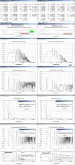
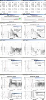
One way to resemble a ‘heard’ situation better visualized is to add an inductance to Le in HR until X (Le)= Re, i.e. adding a 6 dB/ octave pole at the XO point = 80 Hz. (See picture #1)
This is not as steep as you would choose a filter slope in the reality (A 12dB or a sharper LP filter is normally chosen for sub use.) but it’s much better than using no filtering at all, as only the time before about 10mS will hint you if localization cue or image shift will be present and longer pulse time have to be transformed into FR domain before judgeing any timbral effects.
You really want 250 Hz be at minimum 20 dB down before looking at the sub Impulse response. A fake 250 Hz /20 dB down is achieved by placing a 6 dB/octave filter= 20 dB/decade at 25 Hz using a suitable X (Le)= Re at the HR main screen. See the result in picture # 2.
Picture# 3 shows your new design (much more sane than the first you simulated, hint try to keep the compression ratio down, 4:1 at maximum for a aluminum coned driver) but IMO not as good as my suggestions in picture #4. If in the ‘OD’ mode = the driver access lid is completely removed, the T-TQWT is turned into a good Offset Driver TL system too.
b
Attachments
Thanks for pointing out my errors. I am excited that such low group delay, excursion and volume is possible. It's just right for a 3rd order subsonic also.
The OD version is interesting because the sub probably will be placed behind the main speaker, which will be always in a corner. I created a rough model and I hope I can still switch to the TH configuration even though the magnet is pointing outwards, by putting on a lid like you described.
I'm confused about how you measured length difference in one of your older posts. You measured the length of the green line in my picture but according to Hornresp you should use the distances to the listener - their difference is smaller.
Attachments
Thanks for pointing out my errors. I am excited that such low group delay, excursion and volume is possible. It's just right for a 3rd order subsonic also.
The OD version is interesting because the sub probably will be placed behind the main speaker, which will be always in a corner. I created a rough model and I hope I can still switch to the TH configuration even though the magnet is pointing outwards, by putting on a lid like you described.
I'm confused about how you measured length difference in one of your older posts. You measured the length of the green line in my picture but according to Hornresp you should use the distances to the listener - their difference is smaller.
Hi Vadi,
Good choices, I always leave that door open in case of a corner placing of the speaker where a different shallower FR slope is more preferable.
Concerning the FR combining distance: I always use the worst case: about the driver radius or sometime more.
b
Peter,
The "R.I.P." after Bjorno's name indicates he has died, so won't be responding to this decade old thread.
A Qts of 0.36 is "low enough" for a tapped horn.
Drivers may be "overstressed" to failure either mechanically, from excursion, or thermally, from heat, regardless of whether the Qts happens to be 0.2 or 0.4.
Your Hornresp simulation has the information to determine at what frequencies failure modes may be more likely to occur.
- Home
- Loudspeakers
- Subwoofers
- what driver for tapped horn?