Hi,
I´d like to know if anyone has experimented with axial surrounds instead of radial surrounds. They should offer the advantage of larger membrane area with same basket size, and it´ll look cool")
Does anybody know where to get such stuff for a 15" or 18" driver?
jauu
Calvin
I´d like to know if anyone has experimented with axial surrounds instead of radial surrounds. They should offer the advantage of larger membrane area with same basket size, and it´ll look cool
Does anybody know where to get such stuff for a 15" or 18" driver?
jauu
Calvin
An externally hosted image should be here but it was not working when we last tested it.
A normal surround adds sideways stability to the cone, helping to keep the voice coil centred within the magnet assembly. The design you are looking at appears to be less supportive in this direction.
Also, the amount of flex required from the surround would probably be more.
Keep those ideas coming though...
Also, the amount of flex required from the surround would probably be more.
Keep those ideas coming though...
Hi,
thanks, the idea of the axial surround came, becuse of the well known disadvantages of radial surrounds. The stability issue could be coped with a double or even triple spider suspension. Another idea would be to use a radial surround simply because of availabilty, but mounted ´behind´ the diaphragm, so that the membran overlaps the surround. The membrane would need to be shaped appropriately so that the surround could be glued to the membrane lets say ´halfway´ between voicecoil and rim of the membrane.
jauu
Calvin
One of the functions of a surround is to provide an airtight join between the diaphragm and the edge of the enclosure. Mounting the surround inwards of the edge effectively reduces the diaphragm size at low frequencies, because the "sealed" area of the cone is reduced to that of the surround diameter. The cone outboard of the surround simply moves air around its edge, just like a driver in free air.
Some years ago I did see (but not hear) a pair of Japanese origin speakers (JVC? Sharp/Optonica?), part of a "mini system", which had the surround mounted behind the edge of the cone. The actual edge of the cone was very close to the edge of the driver basket, rather like a piston in a cylinder. This would have problems with the trapped air behind the cone edge being forced through the narrow gap as the cone moved in and out. Provided that this did not cause significant noise, it could be used to provide controlled damping to the cone movement, in the manner of a "dashpot".
I suspect the main reason for the half-round radial surround being the most common is simply that an axial surround would be more expensive but not provide enough performance increase to offset the cost. It's cheaper and more impressive to make the driver a little larger to allow for the radial surround's size. Who hasn't looked at a driver with a huge half-round surround and thought, "man, that baby must pump." In any case, a drive with an axial surround, even right on the diaphragm edge, would still need a gap between the diaphragm and the basket to prevent pumping noise.
Hi,
I fully agree with You. One would have to have an eye on the points You mentioned (e.g. the compresion of trapped air volume etc.) and yes it would be more expensive since with the axial surround the driver would be more difficult to mount. It´s not even sure that the axial surrounds advantages would lead to a better behaviour of the driver, too. One of the main reasons for such a construction would be the nice optics. Our subs are globes with opposing cutoff sides. I´d fancy a driver with an outwards curved membrane which would ´complete´ the global looks without the need of a protective grid which You need with a driver of common style.
jauu
Calvin
A current fashion is to make driver cones look like a smooth concave "bowl" by adding a second diaphragm, rather like an enlarged and inverted dustcap. If you leave the domed dustcap/diaphragm facing outwards instead, you would end up with a driver that looks like a dome tweeter. You would need to fit a domed mesh grille to protect it, but this grille could match the curve of the enclosure to complete the sphere outline. Such a cone/dome might not work too well at mid frequencies, but as a sub it should work well.
Addendum to the above:
I think I misunderstood what you are trying to do. On reflection, it appears that you have already thought of a dome diaphragm profile. You are trying to hide the surround to give a cleaner line to such a driver mounted in a spherical enclosure.
But to look good you would need to have the cone edge flush with the basket / driver opening edge. When the cone moved out it would move freely, but when it moved inwards it would enter the cavity and be subject to resistance from the air trapped behind it. (Between the outside of the surround and the basket.) Not good for sound quality...
You could investigate a constrained surround to reduce the necessary gap. Imagine a surround that is much deeper than a half-round, a complete "U" shape. This is not a good shape in free space, as it can collapse under air pressure. But if you mount it so that the "U" is behind the diaphragm face (makes a "groove" betwen the diaphragm and the basket), then you can constrain the surround by having close-fitting cylindrical sides on the diaphragm and the basket.
A crude diagram:
|U| |U|
| | | |
\ ___/
As the cone moves, the surround "rolls" betwen the cylindrical sides of the cone and basket. You could make the cone from expanded foam and give it the desired dome profile to match the enclosure.
Hi,
I thought of a ´hidden´ surround earlier, but preferred the axial surround, because of the fixation ring (Membrane to surround) that has to moulded into or to be glued to the membrane´s backside.
This adds mass where we wouldn´t want additional mass.
But since the membrane coluld be made very stiff using foam, the use of an easy to obtain radial surround could be the decicive design point.
jauu
Calvin
An externally hosted image should be here but it was not working when we last tested it.
Calvin,
You still have the problem of the gap between the diaphragm and the basket. If it is small compared with the volume behind it, you will have problems with non-linear damping of the cone. (More damping on inwards excursions, less on outwards excursions.)
You could use a more complex surround profile that would provide as close as possible to a "constant volume" effect, minimising the change in volume of the trapped air space behind the diaphragm rim and the basket.
Or you could provide a cylindrical rim around the edge of the diaphragm so that it was always within the basket, providing a constant damping. (You could use a constrained surround with this.)
Alterntively, you could investigate a true dome driver architecture, with the voice coil around the edge of the diaphragm. Technics did a similar woofer some years ago with a flat (aerolam) diaphragm. The point is that very large voice coil / magnet assemblies need not be hugely expensive or difficult to manufacture.
Lastly, you could just accept a relatively large gap between the edge of the diaphragm and the basket...
Hi,
im not sure what is meant by ´constrained´ surround.
A true dome structure is out of option, since I´m thinking of 15" to 18" drivers. The BL-product of such a huge coil would be outstanding
but the mass would be too. (for a large driver using a rather small CB mass needed to be high, but that high?)
jauu
Calvin
im not sure what is meant by ´constrained´ surround.
A true dome structure is out of option, since I´m thinking of 15" to 18" drivers. The BL-product of such a huge coil would be outstanding
but the mass would be too. (for a large driver using a rather small CB mass needed to be high, but that high?) jauu
Calvin
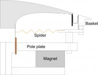
I have attached a modified version of your picture, showing the concept. Such a seal is commonplace in industry where an airtight, low friction seal is needed between, for example, a piston and a cylinder.
It will allow a very small gap between the diaphragm and basket.
The disadvantage is that the edge of the diaphragm will need to have a cylindrical extension to provide one wall of the seal chamber.
I suggested a "true dome" because you can simply extend the cylindrical edge and use it as the voice coil former. The Bl product and weight need not be unmanageable. The field strength in the gap will be lower, because the field is spead over a much longer circumference gap. But the force will be higher, because the wire length in the gap will also be longer. So the Bl product will not be hugely different than a smaller diameter coil.
The moving mass can be lower than you would expect, because the coil and former are much larger and thus have much more area to dissipate heat. They can be constructed more lightly than a conventional VC for the same power.
Finally, if you do have excess Bl, you can make the gap long and the coil short (and thus lower moving mass) and go "underhung".
I have some old Altec drivers that illustrate how effective a light, underhung voice coil can be. They are "Biflex" 15 inch units. The whole cone moves at low frequencies. There is a second surround at about the 8 inch diameter that acts as a mechanical crossover, reducing the effective cone to 8 inch at mid frequencies. Finally, the aluminium dust cap is directly mounted on the voice coil former for HF. It is driven by an extremely light underhung 4 inch voice coil. The driver has a 22 Hz resonance, response to 14 KHz and efficiency of around 95dB.
Attachments
The largest problem with this sort of scheme is that the surround has non-linear compression and expansion, for the first version.
Subsequent suggestions lack the horizontal stabilizing ability of the standard cone. You also have to look at the pressure in the box, especially in the case of a sealed box or a port at resonance... there is a lot of pressure trying to push the diaphragm into non-linear motion.
If you don't believe me, mount up a cone with a surround, no spider and see for yourself how it moves vs. level and vs. frequency.
The question is what is the benefit or goal, other than cosmetic?
Don Hills, any idea what sources there are for such surrounds as the one you showed - I have a very different application (not an audio transducer) that could use some of them in sizes under 8" diameter, but have not been able to locate a reasonable source (off the shelf would be nice).
Thanks,
_-_-bear
Bear:
Yes, at least one (maybe two) spider(s) would be needed.
As I understand it, Calvin wants a narrow gap for aesthetic reasons. He plans a spherical enclosure with the driver diaphragm surface following the same profile as the enclosure. The end result will be a perfect sphere, with only a thin ring marking the edge of the diaphragm.
The only place I have personally seen a seal such as I described was on an old mainframe computer disk drive, where the voicecoil- type head actuator was several inches in diameter and had to have several inches of travel but maintain a dust tight seal. I showed the mechanism to an engineer friend, who commented that he had seen similar seals in linear actuators used in industrial processes. I stripped the actuator to salvage its huge alnico magnets. I now wish I had left it in one piece, it would have been interesting to try driving a huge diaphragm with it as a subwoofer...
As to where you could get such a seal, you could make your own from a strip of thin, flat rubber sheet. Join the ends to form a ring the same diameter as the basket. Next, fold the strip lengthways. It will now have a "U" cross section. Glue one leg of the "U" to the cylindrical edge of the diaphragm, and the other leg to the cylindrical inner edge of the basket. If the difference between the diaphragm diameter and the basket diameter is small (narrow gap), the rubber will not be stretched excessively and will roll smoothly in the gap as the diaphragm moves.
Hi,
Don´s suggestion looks very much like the old Fostex SLE Drivers except of the missing seal with the Fostex.
A very thin gap between the basket and a styrofoam ring connected to the membrane. I´m afraid that there will be audible noise when the driver´s stroke becomes too large, because I don´t think, that the small gap will work as a seal as it is claimed in the Datasheets.
And yes, cosmetics is one of major reasons in this design idea.
Starting point is this subwoofer design:
jauu
Calvin
Don´s suggestion looks very much like the old Fostex SLE Drivers except of the missing seal with the Fostex.
An externally hosted image should be here but it was not working when we last tested it.
A very thin gap between the basket and a styrofoam ring connected to the membrane. I´m afraid that there will be audible noise when the driver´s stroke becomes too large, because I don´t think, that the small gap will work as a seal as it is claimed in the Datasheets.
And yes, cosmetics is one of major reasons in this design idea.
Starting point is this subwoofer design:
An externally hosted image should be here but it was not working when we last tested it.
jauu
Calvin
Another issue with that type of geometry is assembling it. You could probably do it by hand, but even then it would not be easy. Coming form a driver manufacturing background, that would never fly. It would also be very difficult (expensive) to mold compared to typical designs.
From a performance perspective, I've done various types of FEA modeling on suspensions similar to that but not exactly the same and usually the problem is rocking like everyone else mentioned. You can add spiders but that ads depth to the entire speaker. You need the spiders to be separated to be effective at preventing rocking. Another issue you'd have to design around would be self noise from it collapsing on itself - the contact would make noise.
From a performance perspective, I've done various types of FEA modeling on suspensions similar to that but not exactly the same and usually the problem is rocking like everyone else mentioned. You can add spiders but that ads depth to the entire speaker. You need the spiders to be separated to be effective at preventing rocking. Another issue you'd have to design around would be self noise from it collapsing on itself - the contact would make noise.
- Status
- This old topic is closed. If you want to reopen this topic, contact a moderator using the "Report Post" button.
- Home
- Loudspeakers
- Subwoofers
- axial surround instead of radial surround