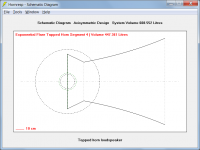
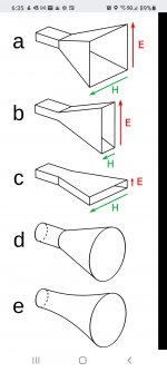
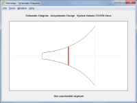
The horn would then have the general form shown in Attachment 2 (not to scale).
Just to clarify - as far as the model used in the actual simulation is concerned, to be theoretically correct, segment 4 should have an exponential flare not a conical one.
I suspect that it won't make much practical difference to the calculated results either way, though.
Attachments
Last edited:
To mimmic the bifuricated design I would design a horn with the appropriate mouth area of one half of the enclosure. I modeled them together using the tools button then multiple speakers. There will be a difference in impedance and therefore SPL due to the choices of series or parallel for the driver impedance.
Hi Mark,
With a bifurcated design, to avoid the differences you mention simply double the cross-sectional areas of one half, and simulate as a single speaker.
Kind regards,
David
Just to clarify - as far as the model used in the actual simulation is concerned, to be theoretically correct, segment 4 should have an exponential flare not a conical one.
I suspect that it won't make much practical difference to the calculated results either way, though.
Looks like all the segments should be parabolic.
Looks like all the segments should be parabolic.
Because segments 1 and 2 have been specified as very short cylinders, the flares chosen for those segments have no meaning, and are therefore disregarded when calculating the results.
The flare of segment 3 is ill-defined, it is neither one thing or the other. Take your pick - your guess is as good as mine
") .
.Because only segment 4 is available to specify the remainder of the system, it needs to be exponential to reflect the overall cross-sectional area expansion rate of the horn.
However:
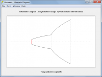
If three segments were available to specify the remainder of the system, then strictly speaking the first and third segments as shown in Attachment 1 should be parabolic. The flare of the middle segment shown in Attachment 1 is ill-defined (similar to segment 3 mentioned above).
Even if parabolic segments were used, the overall flare expansion rate would remain effectively exponential, as can be seen by comparing the profiles of Attachments 2 and 3.
Attachments

Hello,
I apologize for the very basic questions, hopefully they can be answered quickly (I honestly cannot read 1300 pages before I post, I did read a good bunch of the wiki and the hornresp help).
I am trying to model some simple (Vifantastich (see post #155) with TC9FD18) and not so simple (FrugelHorn with FE126En).
I take the driver parameters from loudspeakerdatabase.com, which may be a first isue as I don't have the same parameters as the references on the respective threads.
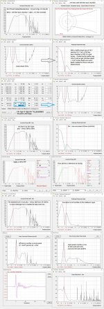
Also there must be other significant errors in my sims, because the results are way off (so much I don't dare to post them) :


Would someone be so kind to post the correct input parameters for either or both loudspeakers ?
Thanks lots in advance
I apologize for the very basic questions, hopefully they can be answered quickly (I honestly cannot read 1300 pages before I post, I did read a good bunch of the wiki and the hornresp help).
I am trying to model some simple (Vifantastich (see post #155) with TC9FD18) and not so simple (FrugelHorn with FE126En).
I take the driver parameters from loudspeakerdatabase.com, which may be a first isue as I don't have the same parameters as the references on the respective threads.
Also there must be other significant errors in my sims, because the results are way off (so much I don't dare to post them) :
Would someone be so kind to post the correct input parameters for either or both loudspeakers ?
Thanks lots in advance
Hi elmans - here's a mass loaded version which might be of help as its response was documented
Flat Wall Mount Stereo MLTL using TC9FD's (2)
Flat Wall Mount Stereo MLTL using TC9FD's (2)
Because segments 1 and 2 have been specified as very short cylinders, the flares chosen for those segments have no meaning, and are therefore disregarded when calculating the results.
The flare of segment 3 is ill-defined, it is neither one thing or the other. Take your pick - your guess is as good as mine
Because only segment 4 is available to specify the remainder of the system, it needs to be exponential to reflect the overall cross-sectional area expansion rate of the horn.
However:
If three segments were available to specify the remainder of the system, then strictly speaking the first and third segments as shown in Attachment 1 should be parabolic. The flare of the middle segment shown in Attachment 1 is ill-defined (similar to segment 3 mentioned above).
Even if parabolic segments were used, the overall flare expansion rate would remain effectively exponential, as can be seen by comparing the profiles of Attachments 2 and 3.
If there are parallel walls (top & bottom or left & right
panels) from the throat to the mouth of a horn, then all the segments are parabolic.
If there are parallel walls (top & bottom or left & right
panels) from the throat to the mouth of a horn, then all the segments are parabolic.
If a segment has two parallel walls and two straight tapered walls then the flare profile for that segment will be parabolic. However, as I attempted to explain and demonstrate in my previous message, in the case of Freddy's Jubilee design we have only one segment to specify the main horn, and it needs to be exponential because the taper rate is not constant over the length of that segment. (I have assumed that Klipsch uses an exponential expansion for the Jubilee, the same as for the original Klipschorn).
B an C are parabolic horns.
Not quite...
If you consider the horns to have two segments each, then the first segment is cylindrical and the second is parabolic. If you try to specify the total horn using just one segment, then you have the same issue as with the Jubilee simulation model.
Rest assured, I know my parabolic horns
.the first segment is cylindrical
Just to clarify, the first segment is considered to be cylindrical even though it may actually be rectangular physically, because it is modelled as axisymmetric in Hornresp.
I don't know if its feasible much less straightforwards
Hi Freddy,
It should certainly be feasible but I am not sure how straightforward it would be. Unless I am missing something it appears to be similar to the Klipsch Jubilee model we considered earlier, and presumably could be constructed in the same way as that speaker.
Kind regards,
David
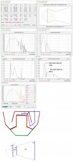
Perhaps the example below will better illustrate the point regarding parabolic horns:
Assume we have a horn made up of two parabolic segments, where
S1 (throat) = 100 cm^2
S2 = 1000 cm^2
S3 (mouth) = 10000 cm^2
L12 (Par) = 50 cm
L23 (Par) = 50 cm
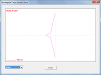
Attachment 1 shows the axisymmetric profile, and Attachment 2 shows the width profile if the horn has a rectangular cross-section with a constant height of 20 cm.
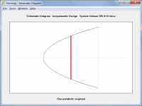
If we have only one segment to specify the horn:
S1 (throat) = 100 cm^2
S2 (mouth) = 10000 cm^2
L12 = 100 cm
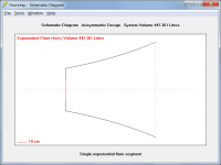
If the flare for the single segment horn is parabolic, as shown in Attachment 3, then the cross-sectional area halfway along the horn works out to be 5050.27 cm^2, not 1000 cm^2 as it was for the two segment case.
If the flare for the single segment horn is exponential, as shown in Attachment 4, then the cross-sectional area halfway along the horn is 1000 cm^2, the same as it was for the two segment case. This profile is therefore a closer approximation to the overall area expansion rate of the horn, particularly in the critical region near the throat, and is the one that should be used.
Assume we have a horn made up of two parabolic segments, where
S1 (throat) = 100 cm^2
S2 = 1000 cm^2
S3 (mouth) = 10000 cm^2
L12 (Par) = 50 cm
L23 (Par) = 50 cm
Attachment 1 shows the axisymmetric profile, and Attachment 2 shows the width profile if the horn has a rectangular cross-section with a constant height of 20 cm.
If we have only one segment to specify the horn:
S1 (throat) = 100 cm^2
S2 (mouth) = 10000 cm^2
L12 = 100 cm
If the flare for the single segment horn is parabolic, as shown in Attachment 3, then the cross-sectional area halfway along the horn works out to be 5050.27 cm^2, not 1000 cm^2 as it was for the two segment case.
If the flare for the single segment horn is exponential, as shown in Attachment 4, then the cross-sectional area halfway along the horn is 1000 cm^2, the same as it was for the two segment case. This profile is therefore a closer approximation to the overall area expansion rate of the horn, particularly in the critical region near the throat, and is the one that should be used.
Attachments
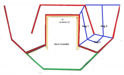
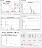
Thanks David - since you say its basically doable -here's some numbers (chamber depth at 100 liters sans driver and ports should be manageable)
With only 93 sq.in. coming into the horn and a 22.5" baffle height. things would be tight (? -like a 5cm spacing from the baffle-throat plate - ??)
What would you suggest to make it "better" without getting out of hand in growth?
With only 93 sq.in. coming into the horn and a 22.5" baffle height. things would be tight (? -like a 5cm spacing from the baffle-throat plate - ??)
What would you suggest to make it "better" without getting out of hand in growth?
Attachments
Last edited:
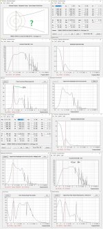
making S4 1.5X that of the previous sim seems a step in the right direction with regards making it work (?)
60% efficiency, even of only a narrow band down pretty low, seems good.
Chamber depth with a 22.5" high baffle would be less than 16" with driver and ports displacement. Speaker size would be around 2 foot high by 3 foot wide by 2 feet deep -(IF the horn fits - lol)
60% efficiency, even of only a narrow band down pretty low, seems good.
Chamber depth with a 22.5" high baffle would be less than 16" with driver and ports displacement. Speaker size would be around 2 foot high by 3 foot wide by 2 feet deep -(IF the horn fits - lol)
Attachments
Last edited:
If the flare for the single segment horn is parabolic, as shown in Attachment 3, then the cross-sectional area halfway along the horn works out to be 5050.27 cm^2
I must need new batteries in my calculator - the half-way area figure quoted should have been 5050.00 cm^2 not 5050.27 cm^2
.Because the cross-sectional area of a parabolic horn expands at a linear rate, at the half-way point it is simply equal to (S1 + S2) / 2. If S1 = 100 and S2 = 10000 then (S1 + S2) / 2 = 5050.
What would you suggest to make it "better" without getting out of hand in growth?
Just keep tweaking the dimensions in the Loudspeaker Wizard - while checking that they remain realistic values. It seems that you are well on the way to doing that already.
- Home
- Loudspeakers
- Subwoofers
- Hornresp