can I list it as a false positive?
Hi GM,
Definitely yet another false positive. Just to check I downloaded and installed a new copy of Hornresp myself, no problems. To make absolutely sure I also ran a separate "On-Demand" virus scan on the downloaded Setup.exe file before installing it - results attached.
Kind regards,
David
Attachments

Thanks! According to Avast, it had just done a 'major' upgrade, so having this situation years ago, figured it had deleted my previous 'false positive', but with all the 'bad' that goes on in the Ethernet, can't be too careful.
Now I can DL it, but get the same BS when I try to run it, then deletes it. I don't remember having to wait on it before. Oh well, got other stuff I can be doing..........
Now I can DL it, but get the same BS when I try to run it, then deletes it.
I don't remember having to wait on it before. Oh well, got other stuff I can be doing..........
Last edited:
you can add an exception - easiest is to add the whole folder as an exception, then it doesn´t matter which version of hornresp you put into it.
to be sure, I just checked the most recent version with virustotal: all clear, not one virus found (using 87 virus scanners)
to be sure, I just checked the most recent version with virustotal: all clear, not one virus found (using 87 virus scanners)

QL factor
Hi david!
is it possible to take into account the QL factor not only for the vented box, but also for other enclosures, such as a quarter-wave resonator/ horn? Hornresp shows different results, if you enter the same enclosure through the horn and through the rear chamber, the difference is in the peak of the resonator. from this we can conclude that hornresp also shows an incorrect frequency response for other enclosures, such as planar horn/BP/horns and others
Attachments
is it possible to take into account the QL factor not only for the vented box, but also for other enclosures, such as a quarter-wave resonator/ horn?
See post linked below:
https://www.diyaudio.com/forums/subwoofers/119854-hornresp-1154.html#post6490957
Hornresp shows different results, if you enter the same enclosure through the horn and through the rear chamber
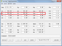
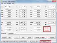
The following changes will make the results identical:
1. Set QL to Lossless when calculating the 'bass reflex' results.
2. Add a 5.47 cm end correction to the back-loaded horn segment 1 'port tube'. This end correction is included automatically when Ap and Lpt are specified in a bass reflex type system. (In attachment 2 the end correction has been added as a second segment - the other way would be to simply increase the length of segment 1 from 169.00 cm to 174.47 cm).
3. Set the path length for the back-loaded horn design to 0.0 cm, to make it the same as that specified for the bass reflex design.
Internal end corrections are added to cylindrical port tubes where Hornresp thinks that they are being used as part of a traditional bass reflex type system. Hornresp does not add a throat end correction to either a horn segment or to a flared port. If no EC details are shown when the mouse pointer is moved over the relevant input parameters, then this means that no internal end correction has been added.
Attachments
Hornresp Update 5310-210718
Hi Everyone,
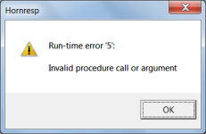
BUG FIX
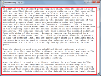
If an existing record was edited and the Input Wizard then used immediately after to create a new record, in some circumstances an error could be generated as shown in the attachment. This bug was introduced when the Input Wizard feature was added in Version 39.90. It has now been fixed.
Kind regards,
David
Hi Everyone,
BUG FIX
If an existing record was edited and the Input Wizard then used immediately after to create a new record, in some circumstances an error could be generated as shown in the attachment. This bug was introduced when the Input Wizard feature was added in Version 39.90. It has now been fixed.
Kind regards,
David
Attachments
How could I run some simulations to a really old horn design?
It is a Shearer horn from the 1930's or so.
I would like to use a Martin Audio DLS846 for it (not clear if its a B&C PZB 46 or a PZB 100)
Just simply don't know what is the best usage of these drivers I got
Martin WSXa (Horn)
Martin S218 (BR)
Or the attached Shearer design?
(or something even better box)
What would be the freq resp?
THX.
Attachments
Hmm, it looks like a Shearer horn, but at a glance its dims don't line up with the original's design: Technical Bulletin, Volume 1936 March 3, 1936 (Shearer).pdf - Google Drive
How could I run some simulations to a really old horn design?
You have the dimensions - specify the horn expansion rate of one of the bifurcated cabinets using four parabolic segments, the total cross-sectional areas of the two acoustic paths, and a single driver. Then simulate two cabinets in parallel.
I was playing with H-Frame and I can't figure out what combined and combined 1 mean.
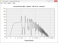
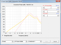
The 'Combined' output option shows the combined power response taking into account the outputs from both sides of the H-frame system. The 'Combined 1' output option shows the same combined power response, together with two additional traces showing the individual power outputs from each side of the system.
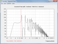
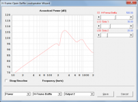
Attachment 1 shows the 'Combined 1' power response for a symmetrical H-frame system. The pink trace shows the combined output 1 + output 2 response, and the yellow trace shows just the output 2 response, as can be seen in Attachment 2. Because in a symmetrical system outputs 1 and 2 are identical, the blue output 1 trace is overlaid exactly by the yellow output 2 trace, which is why only the yellow trace is visible.
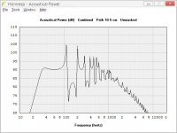
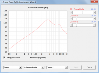
Attachment 3 shows the 'Combined 1' power response for a non-symmetrical H-frame system. The pink trace shows the combined output 1 + output 2 response, the blue trace shows the output 1 response and the yellow trace shows the output 2 response, as can be seen in Attachment 4.
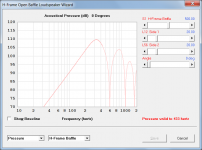
Attachment 5 shows the on-axis pressure response. It can also be calculated at an off-axis angle if required.
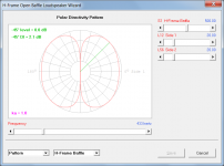
Attachment 6 shows the radiation directivity pattern at a specified frequency.
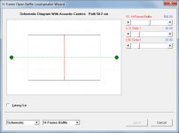
Attachment 7 shows the acoustic centres of the system.
The output from combined does not look right.
'bolserst' has validated the Hornresp predictions against measured results.
Attachments

using its 'find' feature returns nothing for 'combined 1'.
I had assumed that the 'Combined 1' option result would be obvious, but it seems that it is not
.I will look at adding something to the Help file in the next update.
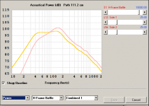
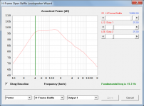
OK thanks David. That helps. I still am kind of scratching my head as to the results I am seeing. The following is an Alpha 15 in a rather large H frame baffle. The results seem to be predicting a 2nd order drop from about 150Hz down to fs and then probably 4th order below that. However people who have listened to this driver seem to relate nearly flat response until fs. Is it really all room gain that makes up the difference?

Attachments
The results seem to be predicting a 2nd order drop from about 150Hz down to fs and then probably 4th order below that. However people who have listened to this driver seem to relate nearly flat response until fs.
Hi mashaffer,
Just speculating, but could it perhaps be that the people who were listening were positioned such that they were hearing the output coming primarily from one side of the system only? The response would then be more like the one shown in Attachment 1.
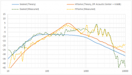
Attachment 2 compares the predicted (solid orange trace) and measured (dotted yellow trace) far-field responses for radiation into 2Pi half-space, obtained by bolserst. As you can see, the results are quite close for ka < 1 (~280Hz).
Kind regards,
David
Attachments
Last edited:
- Home
- Loudspeakers
- Subwoofers
- Hornresp