That said, cylindrical expansion option would be cool just to eliminate entering the area a second time.
It's not going to happen
") .
.Switching to Cyl becomes problematic when editing an existing record, which tends to be what most users do. To illustrate, assume that for the first segment S1 = 100, S2 = 2000 and L12 (Exp) = 100. If Exp is switched to Cyl, does S1 change to 2000 or does S2 change to 100?
Rather than setting a rule I prefer to leave it up to the user to decide which way to go, depending upon the circumstances (ie. whether the segments are stepped, and if not, what area value is required for the throat of segment 2). Besides, there is no real requirement to have a Cyl option as Con, Exp and Par have all been intentionally coded to support S1 = S2.
I was trying to stay within the current parameters of how all the HR fields work to lessen the coding.
It doesn't help. The amount of work that would be required is utterly out of the question. It's not going to happen.
Consider yourself lucky if the Paraflex option is ultimately added (by no means a certainty at this early stage).
Last edited:
It's not going to happen
Switching to Cyl becomes problematic when editing an existing record, which tends to be what most users do. To illustrate, assume that for the first segment S1 = 100, S2 = 2000 and L12 (Exp) = 100. If Exp is switched to Cyl, does S1 change to 2000 or does S2 change to 100?
Rather than setting a rule I prefer to leave it up to the user to decide which way to go, depending upon the circumstances (ie. whether the segments are stepped, and if not, what area value is required for the throat of segment 2). Besides, there is no real requirement to have a Cyl option as Con, Exp and Par have all been intentionally coded to support S1 = S2.
I totally agree with you here. Its not exactly difficult to set the same CSA in both fields and the way its already implemented with S2S, S3S and S4S is way cooler.
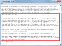
I was thinking about the "throat chamber" conundrum in the putative PA system model and was wondering if the existing "Driver front Volume" calculator be used to define this?
I was thinking about the "throat chamber" conundrum in the putative PA system model and was wondering if the existing "Driver front Volume" calculator be used to define this?
Also trying to work out if SD Vas etc can get us somewhere close to predicting the vtc of a driver flush mounted perpendicular to the path a horn....?
For all sorts of reasons, it's not going to happen.
Is it still worth trying to implement the Paraflex model if driver front volume is not taken into account, bearing in mind that the rear volume occupied by the chassis and magnet assembly is currently disregarded in most cases?
Last edited:
For all sorts of reasons, it's not going to happen.
Is it still worth trying to implement the Paraflex model if driver front volume is not taken into account, bearing in mind that the rear volume occupied by the chassis and magnet assembly is currently disregarded in most cases?
Absolutely. I was just trying to explore if there was a simple way to work around it, I.e. by default its zero (no throat chamber) but if you set the volume in the "Driver Front Volume" popup then that computed CSA, Vtc and Ltc can be used instead.
To be fair I'm surprised someone hasn't suggested an "Export to throat chamber" button for the "Driver Front Volume" popup (for the other system models) already.
I should probably be quiet now and slink off back into the background....
Last edited:
I'm surprised someone hasn't suggested an "Export to throat chamber" button for the "Driver Front Volume" popup (for the other system models) already.
I decided not to do it that way originally because in many designs the driver front volume needs to be added to a separately-specified throat chamber volume, and in other designs there is no throat chamber to export the driver volume to. It would not help with the proposed Paraflex system anyway, because the Vtc and Atc fields in the data record are now used to permanently store the S9 and L89 values, and there are no spare fields left in the record to store exported driver front volume data.
I should probably be quiet now and slink off back into the background....
Yes please! I have so much work ahead of me, the less distractions the better, for a while at least...
.Attachments
Last edited:
It would not help with the proposed Paraflex system anyway, because the Vtc and Atc fields in the data record are now used to permanently store the S9 and L89 values, and there are no spare fields left in the record to store exported driver front volume data.
Very true.
Yes please! I have so much work ahead of me, the less distractions the better, for a while at least...
Once again, thank you so much for looking into this.
 I'll internalise my thoughts and let you crack on.
 I decided not to do it that way originally because in many designs the driver front volume needs to be added to a separately-specified throat chamber volume, and in other designs there is no throat chamber to export the driver volume to.
I knew I had another reason, which I have just remembered
.Depending upon the loudspeaker configuration and the orientation of the driver, it is sometimes necessary to add the driver front volume to Vrc rather than to Vtc.
So there are four possiblities, depending upon the circumstances:
1. Add driver front volume to existing Vtc.
2. Replace existing Vtc with driver front volume.
3. Add driver front volume to existing Vrc.
4. Replace existing Vrc with driver front volume.
Trying to follow the last dialogue here. Didn’t succeed.
And for something completely different, the Previous/Next buttons (and maybe the Edit).
Would it be feasible to get those into the Loudspeaker wizard? That will open up up the possibility to directly jump between the same selected graph for different Records in the project. Very powerful.
And for something completely different, the Previous/Next buttons (and maybe the Edit).
Would it be feasible to get those into the Loudspeaker wizard? That will open up up the possibility to directly jump between the same selected graph for different Records in the project. Very powerful.
Would it be feasible to get those into the Loudspeaker wizard?
No.
Ok,
I see.
I know that there is a save feature in Loudspeaker wizard which is good to use. The “Next” and “Previous” would have been even greater for comparison reasons between different exploration results. Which are starting to get quite a few, with the great fun it is to use the software. But maybe not equally fun to develop
I've installed two instances of Hornresp in seperate directories: Hornresp and Hornresp2That will open up up the possibility to directly jump between the same selected graph for different Records in the project. Very powerful.
This way you can have two Hornresp projects open, makes it easy to compare.
Just pay attention that you're using different .dat files, you can always copy the master .dat of Hornresp to Hornresp2
But maybe not equally fun to develop
You are not wrong there! Things are never as easy to implement as they may appear from the outside, looking in. The current Paraflex project for example, is turning into a real nightmare
.Hey!
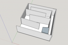
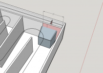
I am trying to duplicate TH-SPUD design with different drivers and model it in Hornresp. Although, i am not sure if i am doing it right. I basically took the "leaked" design of TH-SPUD and put drivers that i have laying around.
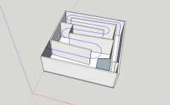
I've made a model in SketchUp which makes it easier to calculate S and L values.
Here is how it will look with Kicker 12" L7 Solobaric woofer:
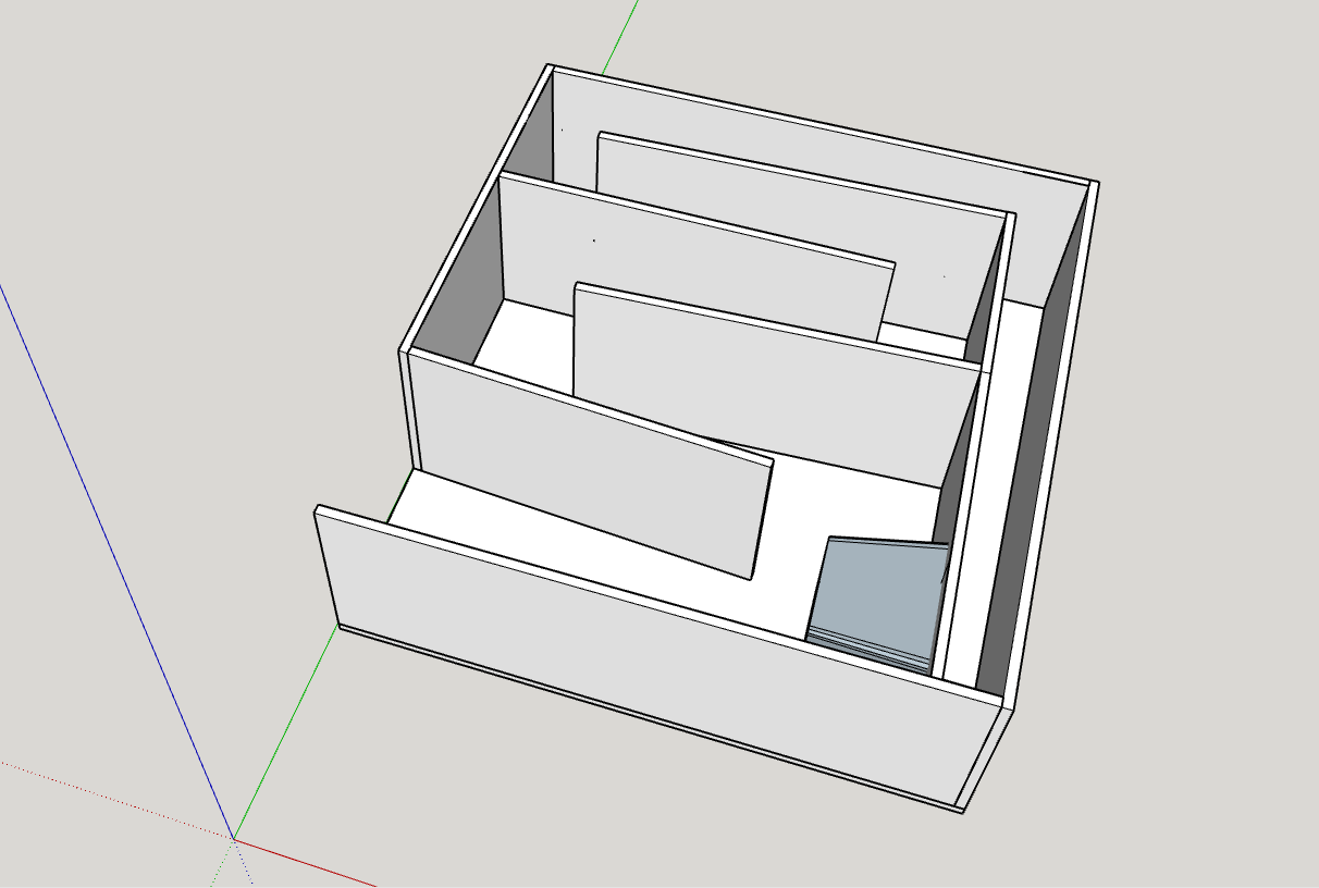
The blue line is how i estimate horn path:
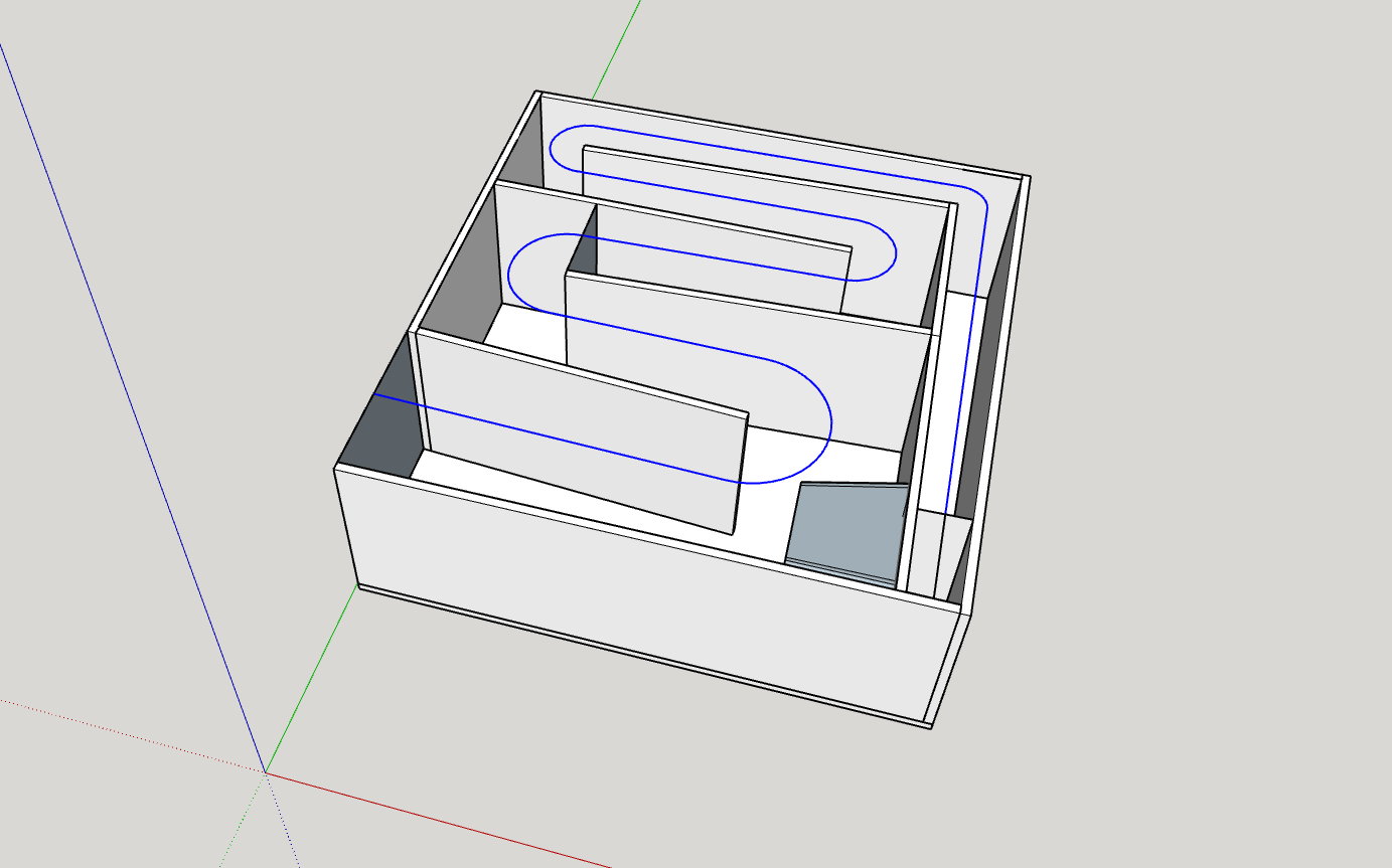
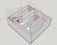
Pale red rectangles is where i put segments of the horn:
Now, i understand that S1 through S3 and even S5 are placed correctly.
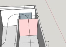
But am i "placing" S4 in the right place?
I am guessing that there are two probable alternatives to where to put it:
Here:

Or here:

This question was probably asked a thousand times before, but i wasn't able to find the answer here.
----
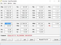
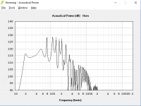
HornResp gives me this estimation (S4 placed as shown in the first example):


Am i really going to get such beautiful response with this tapped horn? Or am i doing something wrong here?
I am trying to duplicate TH-SPUD design with different drivers and model it in Hornresp. Although, i am not sure if i am doing it right. I basically took the "leaked" design of TH-SPUD and put drivers that i have laying around.
I've made a model in SketchUp which makes it easier to calculate S and L values.
Here is how it will look with Kicker 12" L7 Solobaric woofer:
The blue line is how i estimate horn path:
Pale red rectangles is where i put segments of the horn:
Now, i understand that S1 through S3 and even S5 are placed correctly.
But am i "placing" S4 in the right place?
I am guessing that there are two probable alternatives to where to put it:
Here:
Or here:
This question was probably asked a thousand times before, but i wasn't able to find the answer here.
----
HornResp gives me this estimation (S4 placed as shown in the first example):
Am i really going to get such beautiful response with this tapped horn? Or am i doing something wrong here?
Attachments
You are not wrong there! Things are never as easy to implement as they may appear from the outside, looking in. The current Paraflex project for example, is turning into a real nightmare
I know for sure. I’ve been a project/program manager for medium and larger size initiatives in the banking industry for 30+ years. Initiatives till almost always include not only complex processes and requirements. But also from a few to hundreds of different systems on different platforms from way out in different millenniums. That are impacted and should be rebuilt to interact etc etc etc. What you do is amazing and I have full respect of your priorities. I am actually still to a very large extent benefiting on the ability to have the stepped approach wherever in the line for a MLTL. Based on “It will never happen...” I am lucky.
It just seem so damn perfect to just sit there and switch between spls, then move on to impedance etc for different set-ups, way beyond the Save function in Loudspeaker wizard.
But I rest my case!! Thanks again
But am i "placing" S4 in the right place?
Yes.
Hey!
I am trying to duplicate TH-SPUD design with different drivers and model it in Hornresp. Although, i am not sure if i am doing it right. I basically took the "leaked" design of TH-SPUD and put drivers that i have laying around.
The location of S4 is right (i.e. L34 and L45 will be right). However, the value of S4, if you work it out from that slice, might be wrong. You can estimate the correct value for S4 by working out what would be the theoretical cross-section of the path at that distance from S5 or S3.
Use PAR instead of CON sections to describe your design in Hornresp. PAR sections are the correct type to use for a bass horn folded up into a rectangular box.
As this is likely a high Le car audio driver, I suggest deriving the semi-inductance parameters from the driver's impedance curve and using those in the sim to see how its response is impacted.
It just seem so damn perfect to just sit there and switch between spls, then move on to impedance etc for different set-ups, way beyond the Save function in Loudspeaker wizard.
There are currently four completely separate loudspeaker wizard forms, which will become five if the Paraflex model can be made to work. Pressing the Next button in one wizard could become a problem if the next record required a different wizard. There are also other reasons why it is simply not possible to implement the suggestion.
By Save function, I assume that you are referring to the ability to temporarily store and recall up to four different sets of loudspeaker wizard settings, as distinct from clicking the Save button when exiting the wizard?
Ok, I understand. What could seem simple might be complex is not unusual.
Maybe it would be applicable under certain circumstances, what do I know? Now I see that I do what I am trained to do with the great many developers I´ve been orking with throughout the years. "Think another way" without actually saying it. Sorry to do so, a work habit.
Regarding "Save", yes that is what I meant.
- Home
- Loudspeakers
- Subwoofers
- Hornresp