Thanks thomgiles and Matthew Morgan J for your kind words, they give me the strength to carry on. As a first step I will try to analyse the Paraflex standard model equivalent circuit. It may take me a while - I will let you know in due course if I manage to come up with a solution.
Thanks thomgiles and Matthew Morgan J for your kind words, they give me the strength to carry on. As a first step I will try to analyse the Paraflex standard model equivalent circuit. It may take me a while - I will let you know in due course if I manage to come up with a solution.
Thanks David, this means the world to us.
Just so that we are clear, dropping the port "P" nomenclature the system model in reality actual looks like this.
An externally hosted image should be here but it was not working when we last tested it.
Matthew and I also talked about how we could clean up the naming of P1-6 and we think that the following would be much clearer to understand from a User perspective:
For the secondary horn S1-4 would be named R1-4, to reflect the fact that the secondary horn is acting as a resonator to the primary horn. This would be structured so that it visually mirrors the system model:
P1 would be R1 - The equivalent of S1
P2 would be Lo - The equivalent of L12 - Length of offset
P3 would be R3 - The equivalent of S3
P4 would be either Cly / Par / Con / Exp, The equivalent of L23 and the expansion profile between L1-L3.
P5 would be R4 - The equivalent of S4
P6 would be either Cly / Par / Con / Exp, The equivalent of L34 and the expansion profile between L3-L4.
You would then infer the value of R2 from R1/R3, the lengths specified in P2/P4 and the expansion profiles selected in P4. I can sketch this up for you into a short white-paper on monday if you want me to?
Last edited:
In the MLTL with Offset Port module, can you change the path length? Normally it's under Power/Chamber in the Loudspeaker Wizard, but I don't see it there in the MLTL with Offset Port.
Thanks,
Eric
Eric,
Probably you are running an older version of HR. In 51.20 and later you will find a slider for Path in Power/Chamber just above the QL slider. It also gives you the option to Choose Auto Path or Manual Path. In Auto Path the path used is simply the length of the segment(s) between the driver and the port. In Manual you can select whatever path length you choose.
Eric
Eric,
Probably you are running an older version of HR.
Thanks, that was it. Not sure I would ever have figured that out!
Eric
I can sketch this up for you into a short white-paper on monday if you want me to?
Hi thomgiles,
No need for the white-paper, thanks. I think I finally understand...
") .
.If the paraflex feature was to be implemented in Hornresp, for the sake of consistency and established convention I would like to change the designations as detailed below. Hopefully you would be able to live with the changes.
Two questions first:
Q1. I would like to be able to refer to the loudspeaker system as a 'paraflex horn'. Is this an accurate / acceptable description?
If so, then the loudspeaker wizard caption would read 'Paraflex Horn Loudspeaker Wizard' and the loudspeaker configuration code would be PH (for paraflex horn, similar to TH for tapped horn) rather than PA (for paraflex).
Q2. I would like to be able to change the paraflex horn loudspeaker wizard 'Chamber' input option to read 'Resonator' instead. Is this an accurate / acceptable name to use when referring to the sliders associated with the pink-coloured H1, H2 and H3 segment boxes in your system model diagram?
Other proposed changes:
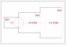
R1 becomes SR1 (S is traditionally used to designate a horn cross-sectional area, R1 could possibly be misinterpreted as a radius)
SR2 to be included in the wizard as an Auto (disabled) slider, so that the user can see the automatically-calculated SR2 area value.
R3 becomes SR3
R4 becomes SR4
Lo becomes L1
'L23' becomes L2 (Con / Cyl / Exp / Par)
'L34' becomes L3 (Con / Cyl / Exp / Par)
In the system schematic, change pink H1 designation to R1, pink H2 to R2 and pink H3 to R3.
The attachment shows how L2 (Cyl) plus L3 (Cyl) would be interpreted. In effect it would allow for the three resonator segments to be stepped, if required.
Would the above changes be acceptable?
Limitations:
1. No absorbent filling material in the three resonator segments.
2. No chambers and/or ports between the driver diaphragm and the horn or resonator, meaning that driver front volume cannot be taken into account directly.
Kind regards,
David
Attachments
Hi David, I'm going to keep this really simple and say yes to everything you have proposed.
I'm aware that loosing the throat chamber will limit the ability to model the volume in the front of the driver but I think this is a fair trade off. People will always have the option of employing standard throat chamber volume correction methods in their physical designs to mitigate this effect.
The only way around this that I can see is by using guess work to approximate the volume occupied by the driver in both horns based on SD, which would probably be wildly inaccurate anyway.
Over the next week I'll instead sketch up some more complicated example user cases to really illustrate the power of this approach and what this would potentially open upto the DIY community.
just consider them additional segments with equivalent naming convention
That would be fine with me Brian, except there would be no S7S or S8S, and L78 and L89 would be Con / Cyl / Exp / Par.
What say you, thomgiles?
That would be fine with me Brian, except there would be no S7S or S8S, and L78 and L89 would be Con / Cyl / Exp / Par.
What say you, thomgiles?
I think that either would work but Brian's suggestion conforms with how a second horn is defined within the existing system models so potentially go with that to avoid ambiguity?
That would be fine with me Brian, except there would be no S7S or S8S, and L78 and L89 would be Con / Cyl / Exp / Par.
So "Cyl" would signify stepped expansion (cylindrical)?
I guess that same terminology can be used for the S1-S5 sections in Hornresp (and so removing the need to highlight the sections in red when they're stepped sections)..
So "Cyl" would signify stepped expansion (cylindrical)?
I guess that same terminology can be used for the S1-S5 sections in Hornresp (and so removing the need to highlight the sections in red when they're stepped sections)..
That thought occurred to me too...
Last edited:
So "Cyl" would signify stepped expansion (cylindrical)?
I guess that same terminology can be used for the S1-S5 sections in Hornresp (and so removing the need to highlight the sections in red when they're stepped sections)..
It wouldn’t remove the stepped mode function, since you can still have steps between segments with expansion. Red highlights forever!
That said, cylindrical expansion option would be cool just to eliminate entering the area a second time.
Chris
Gotta stock up on supplies, Its getting hard to keep up with Tom and David
The double convergent divergent welded pipe, Giles twin chambered octagonalflex and Steele’s DOgFoodDucted corkscrew? it smells like exciting in here!
The double convergent divergent welded pipe, Giles twin chambered octagonalflex and Steele’s DOgFoodDucted corkscrew? it smells like exciting in here!
Attachments

As Paul (Booger weldz) so eloquently put it; Akabak is not the answer for most people. You've developed something here thats amazing and used by thousands of people across the world, ranging from amateur DIY enthusiasts and industry. This tool has literally lead to the evolution of new types of speaker and I'm sure it will continue to do so in the future. We are a very patient bunch and are willing to wait as long as is needed for features like these because they have the potential to solve some of the compounding issues affecting modern speaker designs in a simple, easy to use, accessible UI.
PERFECTLY stated!
Brian's suggestion conforms with how a second horn is defined within the existing system models so potentially go with that to avoid ambiguity?
S6 etc, it will be. That's the designations sorted, now for everything else...
So "Cyl" would signify stepped expansion (cylindrical)?
No. It only means that you could have stepped cylindrical segments in the Paraflex resonator if you wanted to, as shown in Post #11805.
It wouldn’t remove the stepped mode function, since you can still have steps between segments with expansion.
That's why it is the way it is
.BP1Fanatic and thomgiles,
I am still struggling to understand exactly what it is that you are asking for. There are six tapped horn parameters available for possible re-purposing:
P1. Vrc / Ap2
P2. Lrc / Con / Cyl / Exp / Par
P3. Ap / Ap1
P4. Lpt / Lp
P5. Vtc
P6. Atc
Would it be possible to show in diagrammatic form (either schematic, or system model, or both) the configuration or configurations you are seeking, using P1 to P6 designations rather than Vrc, Lrc, etc, and for each configuration, indicating which of the P parameter values used are volumes, which are cross-sectional areas, which are lengths, which lengths are fixed cylindrical, and which lengths are flared?
Actually, I was not trying to rename any fields other than having new function names (TH2 thru TH6). I was trying to stay within the existing HR fields and only move the driver entry point for more segments. That 5th segment is the key to unlimited accurate TH models where the driver can be physically mounted at S2 and S6 or S7.
Example TH2,
Vrc & Lrc = S1-S2 & L12 (which is the beginning of any Nd function model).
Ap & Lpt = S2-S3 & L23 (driver entry point).
Vtc & Atc = S3-S4 & L34 (which is in front of the driver in all HR function models).
S1-S2 & L12 = S4-S5 & L45.
S2-S3 & L23 = S5-S6 & L56.
S3-S4 & L34 = S6-S7 & L67 (driver exit point).
S4-S5 & L45 = S7-S8 & L78.
TH3,
Vrc & Lrc = S1-S2 & L12.
Vtc & Atc = S2-S3 & L23 (driver entry point).
S1-S2 & L12 = S3-S4 & L34.
S2-S3 & L23 = S4-S5 & L45.
S3-S4 & L34 = S5-S6 & L56.
Ap1 & Lpt = S6-S7 & L67 (driver exit point).
S4-S5 & L45 = S7-S8 & L78.
TH4,
Vrc & Lrc = S1-S2 & L12.
Ap2 & Lpt = S2-S3 & L23 (driver entry) and S7-S8 & L78 (driver exit point).
Vtc & Atc = S3-S4 & L34.
S1-S2 & L12 = S4-S5 & L45.
S2-S3 & L23 = S5-S6 & L56.
S3-S4 & L34 = S6-S7 & L67.
S4-S5 & L45 = S8-S9 & L89.
TH5, PF1 or PH1,
Vrc & Lrc = S1-S2 & L12.
Ap2 & Lpt = S2-S3 & L23 (driver entry) and S6-S7 & L67 (exit points).
Vtc & Atc = S3-S4 & L34.
S1-S2 & L12 = S4-S5 & L45.
S2-S3 & L23 = S5-S6 & L56.
S3-S4 & L34 = S7-S8 & L78 (same as stepped CH function).
S4-S5 & L45 = Paraflex vent/port (same as stepped CH function).
TH6, PF2, or PH2,
Vrc & Lrc = S1-S2 & L12.
Ap & Lpt = S2-S3 & L23 (driver entry point).
Vtc & Atc = S3-S4 & L34.
S1-S2 & L12 = S4-S5 & L45.
S2-S3 & L23 = S5-S6 & L56 (driver exit point).
S3-S4 & L34 = S6-S7 & L67 (same as stepped CH function).
S4-S5 & L45 = Paraflex vent/port (same as stepped CH function).
Like I said before, I was trying to stay within the current parameters of how all the HR fields work to lessen the coding.
I just realized all those examples completely jump past 5 segments!
- Home
- Loudspeakers
- Subwoofers
- Hornresp