It doesn't work at the moment, but if all goes according to plan hopefully it will after the next update.
Thanks isn’t as much as I appreciate that, but a hand shake and a cold beer or root beer was sent as a cyber space transmission too sir!
So what have I missed?
Chuffing, lots of chuffing! Particle velocities in the triple digits at s2! Total mayhem and even erosion of trailing edges of rough shapes or inside corner radius creating a downstream affect similar to cavitation on a propeller.

So what have I missed?
Hi just a guy!
It is wonderful to have you back - you have been away almost two years, you know. How is your health now? I had really feared the worst when you suddenly stopped posting in July 2018. In the time that you have been away, Hornresp has gone from Version 46.00 to Version 50.80
./////////////////////////////
Version 46.00 - Closed mouth horn.
Version 47.00 - Bessel horn.
- Acoustical impedance range tool.
Version 48.00 - Fourth order band pass enclosure loudspeaker.
- Sixth order parallel band pass enclosure loudspeaker.
- ABC Ap3 moved from Fr to L34 and Lp3 moved from Tal to F34.
Version 48.10 - Double bass reflex enclosure loudspeaker.
- Room gain in band pass loudspeaker wizard.
Version 48.20 - Open baffle loudspeaker.
Version 48.30 - Standardised BP4 and BP6 enclosures and inputs.
Version 48.40 - Offset driver in BP4 and BP6 enclosures.
- Export band pass, DBR and ABC loudspeaker wizard power, impedance and displacement data.
Version 48.50 - Filter wizard with pressure response.
Version 48.60 - Original Beranek second-harmonic distortion formula corrected.
- Bjørn Kolbrek hyperbolic-exponential distortion correction factor added.
Version 49.00 - Stepped segments.
- Name of database pasted driver added to comment.
- Combined active and equaliser filter gain, phase and group delay.
Version 49.10 - Stepped segments in loudspeaker wizard.
- Closed box loudspeaker with offset driver in input wizard.
- Stepped segments tab sequence changed.
Version 49.20 - Cylindrical zero flare throat adaptor.
Version 49.30 - Driver diaphragm constant rms acceleration.
Version 50.00 - Stubbed horn.
Version 50.10 - Eighth order series band pass enclosure loudspeaker.
- System model acoustic circuit diagram.
Version 50.20 - Fifth order and seventh order band pass enclosure loudspeakers.
Version 50.30 - Ninth order band pass enclosure loudspeaker.
- Band pass, DBR and ABC enclosure passive radiators.
- Band pass, DBR and ABC enclosure port power charts.
- Fundamental resonance frequency marker on particle velocity charts.
Version 50.40 - BP7, BP5 and BP9 changed to BPA, BPB and BPC.
- Driver arrangement tool changed to loudspeaker configuration tool.
- Passive radiator diaphragm displacement chart in band pass loudspeaker wizard.
- Phase and group delay charts in band pass loudspeaker wizard.
- Ctrl plus double-click to switch group delay per period chart.
- Fundamental resonance frequency marker on phase and group delay charts.
- Acoustic centre model for unbaffled driver, driver in finite baffle and driver in H-Frame.
- Advanced driver parameters included in BOXPLAN export file.
- BOXPLAN export file imported into band pass loudspeaker wizard.
Version 50.50 - Flared ME1 and ME2 throat ports in multiple entry horn system.
- Horn 1 and Horn 2 sliders shown together in single segment CH loudspeaker wizard.
Version 50.60 - Horn segment wizard Fta option for exponential and hyperbolic-exponential segments.
- Offset driver with offset port, offset passive radiator or offset stub.
- Dipole pressure response at any angle between 0 and 180 degreees.
- Dipole directivity pattern.
Version 50.70 - Impulse spectrogram frequency range 4 to 1000 hertz.
- Spherical wave horn T flare parameter.
- Vrc cubic centimetre option.
- U-frame cardioid directivity option.
Version 50.80 - System model acoustic circuit diagrams in all loudspeaker wizards.
- Multiple driver BOXPLAN export file imported into loudspeaker wizard.
- L34 Fixed option.
- Double-click Mmp to add mass.
/////////////////////////////
Kind regards,
David
Wow that's a lot. A few of those things I asked for years ago and I'm happy to see them. (OB and offset port.) Steps sound very intriguing too and stubs. And I'm really excited to try semi inductance testing and modeling thanks to you and bolserst.
My health is fine, I'm coming up on 2 years past the last radiation treatment. Of course it could resurface at any moment though.
I haven't done anything audio related in about 3 years and was considering taking it up again. I need a new laptop, mine was mostly trashed way back when I did the inductance (large coil) research so I'll probably order one tomorrow. I was just wondering if I'll recognize hornresp when I download it or if its completely changed. I've been contemplating a couple of projects.
Everything seems fine except when I try to do a max power calc [works fine in the Wizard].
Hi GM,
Thanks for the feedback.
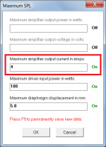
I don't know how you did it, but you managed to end up with no value for the 'maximum amplifier output current in amps' parameter
. It should be 4 amps by default, unless changed to some other value by the user.I have manually corrected your exported file, and it should work fine now.
Not knowing what caused the problem, and just to make sure, I will change Hornresp to automatically insert a value of 4 amps for Imax if it finds that no value exists.
The reason that the wizard worked okay is because it only looks at Pmax and Xmax, so the error in Imax was not seen.
Thanks again for bringing this problem to my attention.
Kind regards,
David
Attachments
My health is fine
I was just wondering if I'll recognize hornresp when I download it
Great to hear that you are in good health - just stay away from COVID-19!
Hornresp still looks the same - only with a few more "bells and whistles" for you to play with...
.So what have I missed?
Welcome back !!!!!
Hornresp Update 5080-200629
Hi Everyone,
CHANGE 1
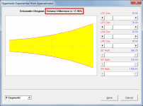
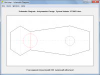
Double-clicking the schematic diagram caption in the Hypex Approximator tool now changes the volume difference from litres to percentage. Attachment 1 refers.
CHANGE 2
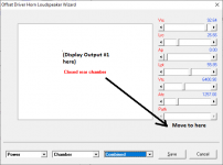
The names of the items listed in the Chamber Type menu are now context-sensitive, and automatically change as necessary to match the descriptions given in the status bar panel at the bottom of the Input Parameters window. Attachment 2 refers.
CHANGE 3
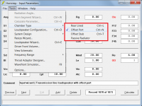
Four-segment closed mouth OD1 systems can now have an offset port, stub or passive radiator. Attachment 3 refers.
CHANGE 4
The maximum amplifier output current value in the Maximum SPL tool is now set to 4 amps if no value exists. Post #10866 refers.
CHANGE 5
When the Loudspeaker Wizard is opened the Schematic Diagram is now displayed first, rather than the System Model.
Kind regards,
David
Hi Everyone,
CHANGE 1
Double-clicking the schematic diagram caption in the Hypex Approximator tool now changes the volume difference from litres to percentage. Attachment 1 refers.
CHANGE 2
The names of the items listed in the Chamber Type menu are now context-sensitive, and automatically change as necessary to match the descriptions given in the status bar panel at the bottom of the Input Parameters window. Attachment 2 refers.
CHANGE 3
Four-segment closed mouth OD1 systems can now have an offset port, stub or passive radiator. Attachment 3 refers.
CHANGE 4
The maximum amplifier output current value in the Maximum SPL tool is now set to 4 amps if no value exists. Post #10866 refers.
CHANGE 5
When the Loudspeaker Wizard is opened the Schematic Diagram is now displayed first, rather than the System Model.
Kind regards,
David
Attachments
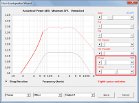
Just a minor suggestion - can the power response of a vented FLH (or basically any sim that has a "combined output" option) be changed so it looks like the attached when the "Combined Output" is selected for viewing and there's no Output #2 (i.e. the chamber is sealed)?
I've got a boxplan design that looks at a sealed FLH than can be optionally changed to a vented FLH, and modifying the Loudspeaker Wizard to show the power response like that would allow the user to leave the Loudspeaker Wizard set to "Combined Response" and just F6 to see how the response changes with any changes in the model exported from BOXPLAN.
I've got a boxplan design that looks at a sealed FLH than can be optionally changed to a vented FLH, and modifying the Loudspeaker Wizard to show the power response like that would allow the user to leave the Loudspeaker Wizard set to "Combined Response" and just F6 to see how the response changes with any changes in the model exported from BOXPLAN.
Attachments
Is there any possibility of inputting a formula for the profile of a segment or throat?
No.
can the power response of a vented FLH (or basically any sim that has a "combined output" option) be changed so it looks like the attached when the "Combined Output" is selected for viewing and there's no Output #2 (i.e. the chamber is sealed)?
I would prefer to leave things the way that they are - less confusing for the user.
can the power response of a vented FLH (or basically any sim that has a "combined output" option) be changed so it looks like the attached when the "Combined Output" is selected for viewing and there's no Output #2 (i.e. the chamber is sealed)?
I think I may have come up with a way to give you what you want while still meeting my "no confusion" requirement. It will however work a bit differently to your suggested method. If no problems arise during testing the new functionality will be included in the next update.
Nice. I've got a beta workbook that I'm working on now that allows (or will allow) the user to switch easily between a sealed or vented FLH. I can send a copy to you via e-mail if you want to use it for experimenting with your method. I can't publish it publicly on my site as the design is a proprietary one and I'd need permission from the owner first.
Red ‘Le’ mode triggers an issue in the OD ‘closed’ sim types where ‘electrical impedance is displayed as the direct radiator equivalent or as if the vent did not exist it seems. It’s fine with black ‘Le’ as far as I can tell. And if I switch the value in black ‘Le’ to the one for ‘Bl’ in red ‘Le’ the results show in Electrical impedance...which may or may not be the equivalent to adjusting Qes by twice, but I’m
not sure how that red ‘Le’ is derived by or implemented upon Bl as inductance otherwise in the SIM
not sure how that red ‘Le’ is derived by or implemented upon Bl as inductance otherwise in the SIM
Last edited:
I can send a copy to you via e-mail if you want to use it for experimenting with your method.
Hi Brian,
A copy of the workbook in .xls format to use during testing would be very helpful, thanks.
Kind regards,
David
- Home
- Loudspeakers
- Subwoofers
- Hornresp