- I guess you selected "close end" somewhere in the design (cant remimber right now where i do that).
Double-click on the Cir or Fta label (not the text box) when in edit mode.
Keep reading the Help file - every feature available in Hornresp is documented there
") .
.Keep reading the Help file - every feature available in Hornresp is documented there
I do I do I do, and I do.....read. Starting from a lot below scratch. I know its all there
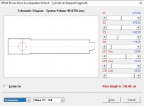
It´s just the work flow for "How to design a tapered MLTL with one driver, one vent, a cylindrical throat segment and a stepped transition to segment two" I am looking at know.
I really know that it´s all there. Like we say in Sweden "it´s in the lake"...
Now I stepped in to the next challenge, that I also think that I have read about in the manual. Having the thepped transition between segment two and three will cause the Loudspeaker wizard creating the third segment to be cylindrical. And also as you pointed out in a previous post (with the comment "And this will not change"). But this will also affect the measurement for the design. Would it be a better way of actually create the first part of the pipe in the design as a chamber?
Or ask for more sliders

Attachments
Last edited:
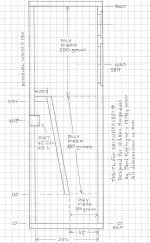
I have now played around wit the software quite a bit. Once you know the principles it´s somewhat easirer. Although I quickly realized that I will not be able to play with my quite simple design that was made up by me with a very intersting and lovely sounding old design as a reference. A design that then got refined in details by Paul Kittinger in MathCad to get the best output, exact measures, graphs etc.
The cylindrical segment 1 and the stepped transition to segment 2 create advantages that can not be simulated in Hornresp as segment 2 gets cylindrical instead of conical in Loudspeaker wizard. Either way, taking away the stepped transition or use the cylindrical segment 2 with some sort of medium area from the originally conical segment 2 creates quite different measures compared to the ones from MathCad.
So from my perspective I will continue to work with the manual, and hope that someone can add on some knowledge to actually add in "how to" sections in it. What I call "work flows".
So if "will not happen" (referring to an earlier post from David ) the type of design that is enclosed here, and contain benefits, will also not happen.
So my humble whish list:
- Updated manual with "How to design a...." step by step description
- More segments (so you dont run out fo them in specific designs)
- Or driver and port positions not directly connected to segment throats/mouths
- A more smooth transition from imput menu to Loudspeaker wizard
- Stepped segment transitions in the wizard (copy of the imput menu design)
Until then - I will work with the manual
And build the MathCad design with the SB17NRX2C35 (and SS2608/91300 plus waveguide used in the Elsinore project)
The cylindrical segment 1 and the stepped transition to segment 2 create advantages that can not be simulated in Hornresp as segment 2 gets cylindrical instead of conical in Loudspeaker wizard. Either way, taking away the stepped transition or use the cylindrical segment 2 with some sort of medium area from the originally conical segment 2 creates quite different measures compared to the ones from MathCad.
So from my perspective I will continue to work with the manual, and hope that someone can add on some knowledge to actually add in "how to" sections in it. What I call "work flows".
So if "will not happen" (referring to an earlier post from David
) the type of design that is enclosed here, and contain benefits, will also not happen.So my humble whish list:
- Updated manual with "How to design a...." step by step description
- More segments (so you dont run out fo them in specific designs)
- Or driver and port positions not directly connected to segment throats/mouths
- A more smooth transition from imput menu to Loudspeaker wizard
- Stepped segment transitions in the wizard (copy of the imput menu design)
Until then - I will work with the manual
And build the MathCad design with the SB17NRX2C35 (and SS2608/91300 plus waveguide used in the Elsinore project)
Attachments
- More segments (so you dont run out fo them in specific designs)
This has been requested so many times that I think David should have the answer in his signature
Would it be a better way of actually create the first part of the pipe in the design as a chamber?
Not if you want an offset driver.
This has been requested so many times that I think David should have the answer in his signature
I guess so.
For me the possibility to work also with the stepped transitions in the wizard is worth ten times more. And if the positioning of the driver(s) and eventual port(s) is ”released” from being positioned by a throat/mouth placement the number of usable segments increase. Both features will increase the usability a lot.
So my humble whish list:
- Updated manual with "How to design a...." step by step description
- More segments (so you dont run out fo them in specific designs)
- Or driver and port positions not directly connected to segment throats/mouths
- A more smooth transition from imput menu to Loudspeaker wizard
- Stepped segment transitions in the wizard (copy of the imput menu design)
None of which are going to happen...
.The Input Wizard can possibly help with the "how to design" part.
More segments would require a complete rewrite of the program.
Have you considered perhaps using AkAbak rather than Hornresp for your simulations?
Rms in HR is asked for as "Newton.sec/m" while Rms in the drivers specs are set to kg/s
The units are equivalent:
Force (N) = Mass (kg) x Acceleration (m/s^2)
N = kg x m/s^2
Rms = N.s/m = [kg x m/s^2] x s/m = kg/s
Last edited:
More segments I can understand will take quite a bit of work. Stepped transition as in my design probably not, and the release of driver/port position from segment throat/mouth depending on how the software is designed. Just guessing.
As this Hornresp thread has over 10000 replies it seemed the best place to go when MathCad is no longer available. Haven’t until now considered any other software. As my design isn’t very special I just thought it would be a piece of cake for the software. But it seem not. And as none of the three changes are on your to do list what so ever it seem that I might reconsider.
As this Hornresp thread has over 10000 replies it seemed the best place to go when MathCad is no longer available. Haven’t until now considered any other software. As my design isn’t very special I just thought it would be a piece of cake for the software. But it seem not. And as none of the three changes are on your to do list what so ever it seem that I might reconsider.
More segments I can understand will take quite a bit of work. Stepped transition as in my design probably not, and the release of driver/port position from segment throat/mouth depending on how the software is designed. Just guessing.
As this Hornresp thread has over 10000 replies it seemed the best place to go when MathCad is no longer available. Haven’t until now considered any other software. As my design isn’t very special I just thought it would be a piece of cake for the software. But it seem not. And as none of the three changes are on your to do list what so ever it seem that I might reconsider.
The situation that you are contemplating is really not required. There were a multitude of comparisons between Akabak and it's ability to micromanage the flow path and the more simplified versions in Hornresp. It turned out that the differences in the end simulations for simple designs like your enclosure are pretty much negligible.
Some times we are so caught up with the little details we try to force a square peg into a round hole.
Hornresp is really one of the most versatile, accurate simulation programs that I have ever used.
I know that many people have validated the simulations. Myself with measurements versus simulations. And I know Bjorn has done much more rigorous validations.
Work with the program. You will be rewarded with a great enclosure if you take time to think within it's abilities.
I don´t know what I am “contemplating”. I realized that the design that I was looking for and know the advantages of didn´t work in the software as-is. That´s how it is, and I might (or might not) ending up somewhere else (probably not).The situation that you are contemplating is really not required.
In this case the differences are definitely not negligible. I am sure Hornresp are doing things at least as good as Akabak and a whole lot more, but my design just didn´t fit.There were a multitude of comparisons between Akabak and its ability to micromanage the flow path and the more simplified versions in Hornresp. It turned out that the differences in the end simulations for simple designs like your enclosure are pretty much negligible.
And it might be so. But the hole is in this case is quite nice. I tried (but failed, with full respect) to get David to carve on the peg so that it did fit. He as the creator has other priorities and who am I to do anything else but being humble and just wish?Some times we are so caught up with the little details we try to force a square peg into a round hole.
Would never ever think of argue against that. That’s why I stepped in here.Hornresp is really one of the most versatile, accurate simulation programs that I have ever used.
This is once again the reason that I stepped in here. It´s a serious work done.I know that many people have validated the simulations. Myself with measurements versus simulations. And I know Bjorn has done much more rigorous validations.
I will surely do that. But not just for this design, as it is already designed to its maximum in MathCad. My aim was that instead of just using the design as-is I was thinking of using this a good start to really going into Hornresp and to the horn principles, “What happens if….” ! Not that I had any expectations to improve the design, but to understand a little bit more than just once again do what someone else had designed for me.Work with the program. You will be rewarded with a great enclosure if you take time to think within its abilities.
Every ten years or so I will remind David about my two most prioritized whishes:
Prio 1 - Stepped transition in whatever cylindrical/conical design in the Loudspeaker wizard
Prio 2 – Release of the driver/vent position from a segment troat/mouth, to make the work smoother and increase the number usable segment without actually re-build the whole software with more segments
Thanks for all the responses and help this far
Last edited:
Sharkythefrog;6221961 In this case the differences are definitely not negligible. I am sure Hornresp are doing things at least as good as Akabak and a whole lot more said:Generally when this is the case you have made an inaccurate simulation. I have found building dozens of enclosures and simulating well over a thousand that this program will simulate pretty close to measured if you build as you simulated and simulate as you build.
For instance your 180 degree bend in the T-line is not required for an accurate simulation if you take a dimension down the centre of the fold.
Your coupling chamber can be accurately modeled.
Almost everything that your design has is included in the simulation that David posted. The only missing part is the stuffing and perhaps a few tweaks to get everything as you originally designed.
And don't feel to overwhelmed.
I have to design a waveguide again that I did 8 years ago bit lost in a computer crash. And I'm having a great bit of fun matching the simulations to the measurements. But I know the program well enough that when I get as close as I can it will be a great design.
The stepped transition S2-S3 can’t be defined together with the conical S3 segment. That’s it. And that makes a defined difference in the measures. David explained that himself, and that it’s not going to change. Can’t be more clear. But I am still happy. Today I have been (and still are 01:29AM) playing with XMachina. Also fun.
Hi David,
Can you verify PR mass setting code ? I feel from comparing sim to measurement that mmp is halved in hornresp.
I play with a kind of 6 order bandpass, with PR one side(45-150hz), and two bandpass box the other side (35-60hz). I use a 94g mmp PR (a CSS APR12). Even if i cannot be sure of real moving mass of the PR, it should not be that far away.
I've done several impedance/response measurement on this box while tweaking. Both response, and impedance spike are in measurement exactly as if my PR moving mass were twice as hornresp input.
I used both OD and BPC to sim, and both gives the same issue (there's of course some response difference due to port end correction between both way).
I tryed to tweak (in box and hornresp) everything, port lenght, amount of stuffing in each cavity, remesured volumes. Everything react as in sim, exepted PR moving mass. I even removed 30g from the PR removing the weight tuning system, so that i have 64g moving mass.
Since this box topology have lot of tweaking capabilities with 3 volumes to tweak stuffing, 2 port lenght to play with, 1 PR weight to tweak, it's not a problem on it own. I just compensate with a smaller bandpass volume behind the PR since i can't reduce anymore PR moving mass, and will just have a bit more loose on PR output than expected.
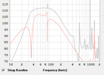
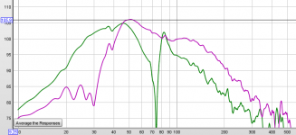
Tweaking right the enclosure, the hole around 75hz on port output (green curve on third picture/red curve in picture 2) is totally removed and response is smooth, both on sim and in real measurements, at different sound levels as expected. I keep those good measurement for the moment, i keep tweaking
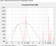
Capture 1 is sims showing in red response of PR with twice PR mass / i grey expected total response (PR+port)
Capture 2 is sims showing in red response of port with twice PR mass / i grey expected total response (PR+port)
Capture 3 is measurement with mic in port entrance (green) / at 5 cm from PR (pink)
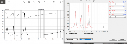
Capture 4 is maybe the most interesting, the simed impedance with twice PR weight in sim in red is exactly what is measured in black.
**Don't overlook at the damped 25hz spike in this measurement set, i just put too much stuffing in back chamber in this arrangement. It can be seen i green curve of picture 3 too that 40hz spike is too much damped.
(I'll post detail of this sub later when it will be finished)
Thank a lot for this awesome tool,
Damien
Can you verify PR mass setting code ? I feel from comparing sim to measurement that mmp is halved in hornresp.
I play with a kind of 6 order bandpass, with PR one side(45-150hz), and two bandpass box the other side (35-60hz). I use a 94g mmp PR (a CSS APR12). Even if i cannot be sure of real moving mass of the PR, it should not be that far away.
I've done several impedance/response measurement on this box while tweaking. Both response, and impedance spike are in measurement exactly as if my PR moving mass were twice as hornresp input.
I used both OD and BPC to sim, and both gives the same issue (there's of course some response difference due to port end correction between both way).
I tryed to tweak (in box and hornresp) everything, port lenght, amount of stuffing in each cavity, remesured volumes. Everything react as in sim, exepted PR moving mass. I even removed 30g from the PR removing the weight tuning system, so that i have 64g moving mass.
Since this box topology have lot of tweaking capabilities with 3 volumes to tweak stuffing, 2 port lenght to play with, 1 PR weight to tweak, it's not a problem on it own. I just compensate with a smaller bandpass volume behind the PR since i can't reduce anymore PR moving mass, and will just have a bit more loose on PR output than expected.
Tweaking right the enclosure, the hole around 75hz on port output (green curve on third picture/red curve in picture 2) is totally removed and response is smooth, both on sim and in real measurements, at different sound levels as expected. I keep those good measurement for the moment, i keep tweaking
Capture 1 is sims showing in red response of PR with twice PR mass / i grey expected total response (PR+port)
Capture 2 is sims showing in red response of port with twice PR mass / i grey expected total response (PR+port)
Capture 3 is measurement with mic in port entrance (green) / at 5 cm from PR (pink)
Capture 4 is maybe the most interesting, the simed impedance with twice PR weight in sim in red is exactly what is measured in black.
**Don't overlook at the damped 25hz spike in this measurement set, i just put too much stuffing in back chamber in this arrangement. It can be seen i green curve of picture 3 too that 40hz spike is too much damped.
(I'll post detail of this sub later when it will be finished)
Thank a lot for this awesome tool,
Damien
Attachments
Last edited:
Can you verify PR mass setting code ? I feel from comparing sim to measurement that mmp is halved in hornresp.
Hi Damien,
Many thanks for the feedback, your observations are very interesting indeed!
I have checked the code as requested, and everything appears to be in order. When I first added the passive radiator option I conducted a number of tests to confirm that Hornresp could get the same results as those generated by Jeff Bagby's Woofer Box and Circuit Designer spreadsheet:
Loudspeaker Design Software
I have again checked against the spreadsheet and everything still agrees. If I double the added mass in Hornresp however, the results no longer compare well.
Just to clarify - when you say Mmp, I assume you are referring to the total mass - that is, the passive radiator Mmp parameter value plus any user-specified added mass?
Kind regards,
David
Last edited:
Yes exactly. I tryed from no added mass (as i need around 90g from sim) to 1200g for burn-in. Cone of PR seems really hard (so heavy ?), but it would be such a variation from factory value. I'll try remove more of their the plastic kind voicecoil former (cone to spider material) to get mass lower again. So from your observation, it must be the effect of PR parameters being really wrong + my added little construction variations from sim.
I keep a bit septical, and will verify with akabak when i'll be motavated, because when i tryed to get same response from hornresp and akabak, i didn't manage PR systems to get same result. But Akabak is such a pain for a "sunday handyman" (does this expression exist in english?) like me.
Thanks a lot David for your expertise !
Last edited:
will verify with akabak when i'll be motavated, because when i tryed to get same response from hornresp and akabak, i didn't manage PR systems to get same result.
That would be great, thanks.
If the AkAbak combined power response results are different, then perhaps there is something wrong with the Hornresp passive radiator model, even though it produces results similar to Jeff Bagby's spreadsheet.
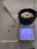
Ok i finally removed the last part of plastic weight tuning system of the PR, it weight on it own more than 50g ! It is really thick...so, hornresp was right, as always. It's the PR datasheet that was misleading ! Sorry for having doubt about hornresp !
Attachments
Last edited:
That would be great, thanks.
If the AkAbak combined power response results are different, then perhaps there is something wrong with the Hornresp passive radiator model, even though it produces results similar to Jeff Bagby's spreadsheet.
Maybe compare it to Unibox. Much more accurate in modeling passive radiators.
I have found the Bagby software to be a strange duck. Also I know other pros who refuse to use it. Same comments from these guys. It has a few flaws that I know for a fact were pointed out, and yet never were addressed.
Unibox has bee one heavy hitter for years that seems to get overlooked for standard box simulations.
Sorry for having doubt about hornresp !
Not a problem
.It's good to be able to do double-checks like these, to confirm that the Hornresp passive radiator model is working correctly.
- Home
- Loudspeakers
- Subwoofers
- Hornresp