I will pull together some details this weekend.
Many thanks!
Hello,
today, when I wanted to use hornresp on my computer "win10 64bit", the icon in the quick launch bar had disappeared, in the folder, hornresp.exe too. I downloaded it again from the site, but windows do not install it because according to defender, there is a trojan,I add a screenshot.
I have the same version of software on a "win7 32bit" and there is no problem. You have an explanation, thank you.
Best regards,
Stefano
Attachments
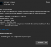
I downloaded it again from the site, but windows do not install it because according to defender, there is a trojan
Hi Stefano,
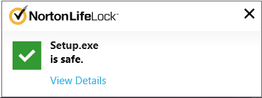
Just to check, I downloaded a copy of Hornresp myself to confirm that it has not been hacked in some way. Everything works fine for me. It seems that the antivirus software on your Windows 10 computer does not trust the executable files Setup.exe and Hornresp.exe for some reason, even though they are totally safe. I am no expert when it comes to such things, so am not really in a position to assist you in a meaningful way. Hopefully someone with more knowledge in such matters may be able to step in and offer some suggestions.
Sorry I can't be of more help...
Stay safe,
David
Attachments
I have HornResp installed on Windows10 Pro and Defender throws the non-trusted error because it's from an "unknown publisher". I also have Windows7 Pro with TrendMicro Antivirus and it does this as well. It's not really a problem.
Right click on the Setup file and select "run as Administrator".
When the Win10 Defender pop up window appears, select "more info" (it's underlined).
In the new popup window select "Run Anyway" (bottom right).
Are you're good to go. If you have another antivirus program installed with Defender (like Trend), you will have to do this 2x in a row to get past both antivirus programs.
Right click on the Setup file and select "run as Administrator".
When the Win10 Defender pop up window appears, select "more info" (it's underlined).
In the new popup window select "Run Anyway" (bottom right).
Thanks Don, for helping out.
i removed all the defender filters, reinstalled the same hornresp, everything works as before, thank you.
Excellent
") .
.I just wanted to thank you
Thanks Damien. Take care, and stay safe.
I am designing a line arrey type box, and I intend to put the air vents on the sides of the box, what type of problems will I have or not so much influence ??
Hi Robson,
As previously advised, it is not possible to accurately simulate a line array type system using Hornresp.
https://www.diyaudio.com/forums/subwoofers/119854-hornresp-1050.html#post6091392
In general though, the precise location of the port tube in a cabinet is not normally an issue at bass frequencies - particularly if the distance (acoustic path length) between the two sources (the sound outputs from the direct radiator and port) is taken into account.
Stay safe,
David
Hi Stefano,
Just to check, I downloaded a copy of Hornresp myself to confirm that it has not been hacked in some way. Everything works fine for me. It seems that the antivirus software on your Windows 10 computer does not trust the executable files Setup.exe and Hornresp.exe for some reason, even though they are totally safe. I am no expert when it comes to such things, so am not really in a position to assist you in a meaningful way. Hopefully someone with more knowledge in such matters may be able to step in and offer some suggestions.
Sorry I can't be of more help...
Stay safe,
David
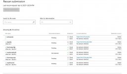
Avast also detected Hornresp as a "suspicious file" but after automatically uploading the file to their servers and checking, it no longer obstructs the installation.
If I understand correct, Hornresp FR plots are at a distance of 1m and angle of 0 degrees on axis. Is it possible to program a feature such that the output at a given angle and distance can be plotted?
Hi Giri,
The Hornresp acoustical power chart shows the pressure response at 1 metre for a point source radiating the total sound power produced by the system. The results are independent of the off-axis angle.
The Hornresp acoustical pressure chart shows the pressure response at 1 metre for a direct radiating single driver or single-segment horn. The off-axis angle can be specified. The acoustical pressure chart is selected using the Directivity Response tool.
The following formula can be used to calculate the output level at a distance other than 1 metre.
SPL(D) = SPL(1) + 20 * Log10(1 / D)
Where:
SPL(D) = SPL at a distance of D metres
SPL(1) = SPL at a distance of 1 metre
For example, if SPL(1) = 100 dB then SPL(10) = 80 dB
Stay safe,
David
Thank you, David
have the length of the last segment be dependent on the offset e.g., if L34 represents the offset, then increasing L34 should decrease L23. Adlusting L23 should not impact L34 though. This will allow for changing the port offset without changing the total volume of the sim.
In a three segment system the port position will be adjusted using L23 rather than L34, so that the port will move in the same direction as the L23 slider. As L23 is increased L34 will decrease to keep the overall length constant. S3 will be able to be set to Auto so that the total volume remains constant. Adjusting L34 will not change the values of L12 or L23.
Moving the L23 slider to the right will move the offset port to the right on the schematic diagram, which makes the operation more intuitive, and consistent with how the L12 slider controls the movement of the offset driver.
Hi Giri,
The Hornresp acoustical power chart shows the pressure response at 1 metre for a point source radiating the total sound power produced by the system. The results are independent of the off-axis angle.
The Hornresp acoustical pressure chart shows the pressure response at 1 metre for a direct radiating single driver or single-segment horn. The off-axis angle can be specified. The acoustical pressure chart is selected using the Directivity Response tool.
The following formula can be used to calculate the output level at a distance other than 1 metre.
SPL(D) = SPL(1) + 20 * Log10(1 / D)
Where:
SPL(D) = SPL at a distance of D metres
SPL(1) = SPL at a distance of 1 metre
For example, if SPL(1) = 100 dB then SPL(10) = 80 dB
Stay safe,
David
Just one more question. Do these calculations apply to OB, U-frame and H- frame woofers?
Do these calculations apply to OB, U-frame and H- frame woofers?
Yes, if the systems are assumed to be point sources.
Note also that the formula can be generalised so that the reference distance does not necessarily have to be 1 metre, and that the formula can also calculate SPL at a point less than the reference distance, if required.
The generalised formula is:
SPL(D) = SPL(R) + 20 * Log10(R / D)
Where:
SPL(D) = SPL at a distance of D metres
SPL(R) = SPL at a reference distance of R metres
For example, if SPL(R) at 5 metres = 100 dB then SPL(D) at 10 metres = 93.98 dB and SPL(D) at 2 metres = 107.96 dB
Hi David
I have a question regarding combining different horn profiles in hornresp.
I have only scratched the surface as far as using hornresp. I’ve read the kickstart article and referred to the help file to try my best to figure out what I wanted to try modeling. I’ve been tinkering with it on and off for a few years and was able to model some different horn profiles and drivers successfully... albeit without knowing if they are truly optimal scenarios.
I’ve been experimenting with front horns now for several years and have a few different pairs of horns that I have purchased used.
The ideas I’ve had for expanding my experience with horns revolve around modifying and repurposing what I already have in order to reduce the amount of fabrication needed to try different horn/driver combinations.
Until now I have used one of two pairs of Oris horns in combination with 8” full range drivers (i.e. Fostex, Lowther, Tang Band). The results have been very good.
The Oris horns are the model 200. They are supposed to be based on a “modified” Tractrix profile. According to what I have read on this subject the “modified” part appears to have more to do with how they are terminated at the mouth.
It seems the degree of round over at the mouth was a subjective decision not following strict calculations. I have two pair of these horns with entirely different profiles at mouth termination.
It is very possible one pair of these horns could be a copy as I do not entirely know about its origins. Yet they measure the same dimensions at the throat and also if the mouth measurement is taken at the center of their mouth termination roll over. I’ve also measured them at a few specific points along their profiles and they appear to match. Sorry...I digress.
My desire would be to take the extra pair of these tractrix horns that I’m not currently using and build a conical throat extension that could be attached to it so that I could try using it in a few different ways. One would be as a mid bass horn with one or two B&C 8PE21 drivers. A second would be a multi-entry variant also with a conical profile that would use a pair of B&C 8PE21 drivers and either a Radian 760neoPb or Dynaudio D54.
The conical profile would simply be the easiest thing to build given that these are experiments and the multi entry scenario would require a flat geometry on the exterior in order to mount the drivers.
I figured I would be able to build these from MDF and then use body filler or polyester resin along with a round conical plug form to match the internal transition of the conical mouth to the round tractrix throat.
The only thing I have been able to model in hornresp so far is a multi segment horn that creates a throat adapter for the B&C driver using S1 (which uses quite a bit of compression due to a small throat size...I couldn’t figure out the right way to do this) and the conical profile for the adapter with S2 which matches the throat size of the Tractrix horn. At that point I have only been able to try approximating the Tractrix horn segment with S3 by using the same throat, mouth and length dimensions albeit with an exponential profile. I think I also came up with a different combination that might have allowed a hyperbolic approximation?
So my very long winded explanation and question is:
Is there a way to model a multi segment horn that starts with a conical (or other profile) horn segment and ends with a Tractrix profile in the last segment?
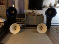
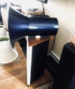
I added some pics of the horns in question.
P.S. The initial idea was to reuse the white Oris horns in this manner as midbass horns with the B&C drivers and try to pass them off to a pair of 350Hz Edgar horns that I have using either the D54 or 760neoPb.
I have a question regarding combining different horn profiles in hornresp.
I have only scratched the surface as far as using hornresp. I’ve read the kickstart article and referred to the help file to try my best to figure out what I wanted to try modeling. I’ve been tinkering with it on and off for a few years and was able to model some different horn profiles and drivers successfully... albeit without knowing if they are truly optimal scenarios.
I’ve been experimenting with front horns now for several years and have a few different pairs of horns that I have purchased used.
The ideas I’ve had for expanding my experience with horns revolve around modifying and repurposing what I already have in order to reduce the amount of fabrication needed to try different horn/driver combinations.
Until now I have used one of two pairs of Oris horns in combination with 8” full range drivers (i.e. Fostex, Lowther, Tang Band). The results have been very good.
The Oris horns are the model 200. They are supposed to be based on a “modified” Tractrix profile. According to what I have read on this subject the “modified” part appears to have more to do with how they are terminated at the mouth.
It seems the degree of round over at the mouth was a subjective decision not following strict calculations. I have two pair of these horns with entirely different profiles at mouth termination.
It is very possible one pair of these horns could be a copy as I do not entirely know about its origins. Yet they measure the same dimensions at the throat and also if the mouth measurement is taken at the center of their mouth termination roll over. I’ve also measured them at a few specific points along their profiles and they appear to match. Sorry...I digress.
My desire would be to take the extra pair of these tractrix horns that I’m not currently using and build a conical throat extension that could be attached to it so that I could try using it in a few different ways. One would be as a mid bass horn with one or two B&C 8PE21 drivers. A second would be a multi-entry variant also with a conical profile that would use a pair of B&C 8PE21 drivers and either a Radian 760neoPb or Dynaudio D54.
The conical profile would simply be the easiest thing to build given that these are experiments and the multi entry scenario would require a flat geometry on the exterior in order to mount the drivers.
I figured I would be able to build these from MDF and then use body filler or polyester resin along with a round conical plug form to match the internal transition of the conical mouth to the round tractrix throat.
The only thing I have been able to model in hornresp so far is a multi segment horn that creates a throat adapter for the B&C driver using S1 (which uses quite a bit of compression due to a small throat size...I couldn’t figure out the right way to do this) and the conical profile for the adapter with S2 which matches the throat size of the Tractrix horn. At that point I have only been able to try approximating the Tractrix horn segment with S3 by using the same throat, mouth and length dimensions albeit with an exponential profile. I think I also came up with a different combination that might have allowed a hyperbolic approximation?
So my very long winded explanation and question is:
Is there a way to model a multi segment horn that starts with a conical (or other profile) horn segment and ends with a Tractrix profile in the last segment?
I added some pics of the horns in question.
P.S. The initial idea was to reuse the white Oris horns in this manner as midbass horns with the B&C drivers and try to pass them off to a pair of 350Hz Edgar horns that I have using either the D54 or 760neoPb.
Attachments

- Home
- Loudspeakers
- Subwoofers
- Hornresp