In the case of a tapped horn a throat chamber port can be specified, but it is not a fifth segment.
I knew that option. Thank you anyways David! HR is still the best software EVER!
In the case of a tapped horn a throat chamber port can be specified, but it is not a fifth segment.
That's all I can come up with to.
It's something. But not a real segment.
You just need a really big throat chamber!

Hornresp Update 5050-200115
Hi Everyone,
CHANGE
The resonance frequency issue reported by Giri in Post #10353 and followed up in Post #10370, has now been fixed.
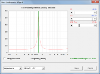
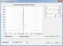
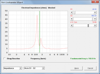
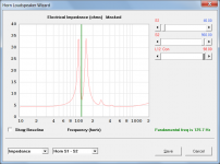
Note that while "false positives" triggering erroneous frequencies can no longer occur, it is still possible in some circumstances for the resonance frequency to "jump" when a slight alteration is made to an input parameter value. This now only happens at the critical crossover point where the loudspeaker system transitions from exhibiting the characteristics of a parallel resonant circuit (high impedance at resonance) to one exhibiting the characteristics of a series resonant circuit (low impedance at resonance). This step-change is to be expected, and is not caused by a bug.
To illustrate the behaviour, the attachments show how the resonance characteristics transition for a given test example as L12 is increased from 27.00 (parallel) to 98.00 (series), with the crossover or "jump" occurring at the point where L12 changes from 74.70 to 74.80.
My thanks to Giri for reporting the resonance frequency issue.
Kind regards,
David
Hi Everyone,
CHANGE
The resonance frequency issue reported by Giri in Post #10353 and followed up in Post #10370, has now been fixed.
Note that while "false positives" triggering erroneous frequencies can no longer occur, it is still possible in some circumstances for the resonance frequency to "jump" when a slight alteration is made to an input parameter value. This now only happens at the critical crossover point where the loudspeaker system transitions from exhibiting the characteristics of a parallel resonant circuit (high impedance at resonance) to one exhibiting the characteristics of a series resonant circuit (low impedance at resonance). This step-change is to be expected, and is not caused by a bug.
To illustrate the behaviour, the attachments show how the resonance characteristics transition for a given test example as L12 is increased from 27.00 (parallel) to 98.00 (series), with the crossover or "jump" occurring at the point where L12 changes from 74.70 to 74.80.
My thanks to Giri for reporting the resonance frequency issue.
Kind regards,
David
Attachments
David it goes without saying you are an immensely generous chap with what you are doing here for us all.
For me the added benefit is the generous sharing of knowledge - case example "This step-change is to be expected" - I had no idea this would be expected so I learnt something then.
Thank you!
For me the added benefit is the generous sharing of knowledge - case example "This step-change is to be expected" - I had no idea this would be expected so I learnt something then.
Thank you!
"This step-change is to be expected" - I had no idea this would be expected so I learnt something then.
Hi Mazza,
Just to clarify - the step-change is to be expected only in the context of how Hornresp determines the theoretical resonant frequency. Your guess is as good as mine as to what actually happens to the system resonance during such an impedance transition, in a real loudspeaker
.Kind regards,
David
Hi David,
A questions, up to which frequency the simulation is correct?
I'am simulating a full-range MLTL with the Dayton RS100-8 and I obtain this results:

The valley in the region of 600Hz that is present in the simulation, will be present also in the real speaker? Because in the real TL will be not straight.
Thank you very much!
A questions, up to which frequency the simulation is correct?
I'am simulating a full-range MLTL with the Dayton RS100-8 and I obtain this results:
The valley in the region of 600Hz that is present in the simulation, will be present also in the real speaker? Because in the real TL will be not straight.
Thank you very much!
Last edited:
The valley in the region of 600Hz that is present in the simulation, will be present also in the real speaker?
Hi Bambinz,
It is difficult to say, not knowing what is causing the dip in the predicted response in the first place. The Hornresp simulation model assumes that the transmission line is a straight axisymmetric duct, and that the driver is a rigid plane piston. Any deviation from these assumptions in the actual built loudspeaker will mean that there will be a difference between the measured results and the predictions. How much of a difference there will be in the case of your system, I don't really know.
You question could perhaps be best answered by someone who has already built a system similar to the one you propose.
Kind regards,
David

Hornresp Update 5050-200124
Hi Everyone,
CHANGE
Further to Post #10383, ongoing testing revealed that it was still possible for erroneous resonance frequency results to be generated in some 'extreme' cases. Changes have now been made which hopefully will further reduce the chances of such errors occurring in the future.
Kind regards,
David
Hi Bambinz,
Thanks for the thanks.
Unfortunately it seems that it is not possible to completely eliminate the chances of erroneous resonance frequency values being displayed from time to time, but the latest release is hopefully another step in the right direction. In any event, it should now be pretty obvious to users when the value is wrong.
If anyone knows of a foolproof algorithm to determine the theoretical fundamental resonance frequency of a given loudspeaker system, then I would be very interested in learning more.
Kind regards,
David
Thanks for the thanks
.Unfortunately it seems that it is not possible to completely eliminate the chances of erroneous resonance frequency values being displayed from time to time, but the latest release is hopefully another step in the right direction. In any event, it should now be pretty obvious to users when the value is wrong.
If anyone knows of a foolproof algorithm to determine the theoretical fundamental resonance frequency of a given loudspeaker system, then I would be very interested in learning more.
Kind regards,
David
If the error is popping up only in extreme (non realistic) scenarios, you could consider a different approach and put limits and checks on the input values entered by the user.Hi Bambinz,
Thanks for the thanks
Unfortunately it seems that it is not possible to completely eliminate the chances of erroneous resonance frequency values being displayed from time to time, but the latest release is hopefully another step in the right direction. In any event, it should now be pretty obvious to users when the value is wrong.
If anyone knows of a foolproof algorithm to determine the theoretical fundamental resonance frequency of a given loudspeaker system, then I would be very interested in learning more.
Kind regards,
David
Could we get a status bar at the bottom for the various calculator windows as well? Maybe some tips on what the parameters mean and how to use the calculator?
Hi Mark,
Technically speaking, the resonance frequency problem was not really due to a bug. The algorithm was working as intended, but the detection method used in the algorithm was simply not capable of accurately identifying the correct resonance point in all cases.
The latest algorithm should work fine with your band pass enclosure designs. The problem seems to occur mainly with 'extreme' front-loaded and back-loaded horns.
Kind regards,
David
Thanks for swatting the bugs David!
Technically speaking, the resonance frequency problem was not really due to a bug
. The algorithm was working as intended, but the detection method used in the algorithm was simply not capable of accurately identifying the correct resonance point in all cases.Have to work on some PA bandpass boxes for a client.
The latest algorithm should work fine with your band pass enclosure designs. The problem seems to occur mainly with 'extreme' front-loaded and back-loaded horns.
Kind regards,
David
Hi SamAnytime,
It's not the individual input values that are the problem, but rather the overall combination of values - and then only when they result in the specification of an unrealistic design. There is really no way of knowing what the limits and checks should be, as it will all depend upon the total system specification.
Just to clarify - what calculators were you thinking of?
Kind regards,
David
you could consider a different approach and put limits and checks on the input values entered by the user.
It's not the individual input values that are the problem, but rather the overall combination of values - and then only when they result in the specification of an unrealistic design. There is really no way of knowing what the limits and checks should be, as it will all depend upon the total system specification.
Could we get a status bar at the bottom for the various calculator windows as well? Maybe some tips on what the parameters mean and how to use the calculator?
Just to clarify - what calculators were you thinking of?
Kind regards,
David
Hi David,
A questions, up to which frequency the simulation is correct?
I'am simulating a full-range MLTL with the Dayton RS100-8 and I obtain this results:
The valley in the region of 600Hz that is present in the simulation, will be present also in the real speaker? Because in the real TL will be not straight.
Thank you very much!
Try simulate with damping material. Fill the closed end of the pipe up to the speaker. With damping material you will be handle higher order harmonics.
Without damping the real speaker will not be usable above maybe 500 Hz.
The windows that pop up when we click a field on the 'input parameters' window. E.g. the fields for the first segment causes a window to pop up which has fields like S1, S2, L12, etc. along with a few radio buttons and a few command buttons.Hi SamAnytime,
Just to clarify - what calculators were you thinking of?
Kind regards,David
- Home
- Loudspeakers
- Subwoofers
- Hornresp