Maybe, it could be integrated in someway to Hornresp
Hi Marcelo,
I am not exactly sure what it is that you have in mind could be integrated.
Kind regards,
David
You should have written this on a card
No time for writing on cards - I'm kept fully occupied fixing all the bugs you keep finding...
") .
.Hi Andypk,
The height dimensions of your constructed horn should be two times the Height/2 values, and the width dimension two times the Width/2 value. Your "as constructed" internal width of 42 cm is correct, but unfortunately it would seem that the height values (and therefore the overall cross-sectional areas) are half what they should be, making the overall horn cabinet smaller than the size required for the given design.
David
So the horn needs to be mirrored in the Y-axis
or..
height x 2 to keep the X-axis straight line. Thank you!
THANK YOU DAVID !Hi Everyone,
BUG FIX
The problem reported by Damien in Post #10264 has now been fixed.
Kind regards,
David
Stuffing seems to works soooo well for mid ports that i won't even try to experiment with port shape/orientation. Mid power capabilites not beeing a issue, efficiency loose from stuffing for mid is a compromise that i can accept really easily in exchange of reduced resonnances. And it add high pass effect on mid, that freely somewhat protect from over excursion. Awesome.

I am not exactly sure what it is that you have in mind could be integrated.
I thought about something simple and useful like add "reference line" at port outlet particle velocity chart that may help user to evaluate the design regarding potential noise.
See the example below. You could also add tooltips in some cases to guide users.
Attachments
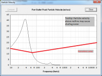
Another way to do it would be to change the color of the graph line to red when the velocity gets too high. Or change the background of the graph to light red to designate that particular area where particle velocity can be an issue if the graph line extends into that area.
I thought about something simple and useful like add "reference line" at port outlet particle velocity chart that may help user to evaluate the design regarding potential noise.
Thanks for the clarification.
If someone can provide me with the equation to use to plot the limiting "reference line" particle velocity for a single, circular, unflared port tube, as a function of frequency and port diameter, then I can certainly have a look at doing something with it.
User Collo did the flare it tool if I'm not wrong. It's in VB6 ^^. Maybe should he give you all you need. I use hornresp with Flare-it tool as guideline for port sizing.Thanks for the clarification.
If someone can provide me with the equation to use to plot the limiting "reference line" particle velocity for a single, circular, unflared port tube, as a function of frequency and port diameter, then I can certainly have a look at doing something with it.
If I'm not wrong he still come and recently wrote on diyaudio.
Last edited:
User Collo did the flare it tool if I'm not wrong.
Flare-it appears to be limited to spot frequencies of 20Hz, 25Hz, 30Hz and 35Hz. Hornresp would require frequencies from 10Hz to 20kHz.
Maybe it is better to keep it separate from hornresp
A great suggestion.
Saves me having to do any more work until someone develops a suitable model
.Maybe it is better to keep it separate from hornresp until a chuffing and port compression model comes to life.
There are a few papers that seem to address this. I did a quick look yesterday. My math powers are more than a little rusty. I'll try to sift through them over the next few days.
Dear Mr. McBean,
I have looked and I cannot find WHAT a closed box with offset driver enclosure is.
Could you direct me to where this is explained?
I assumed it was simply a closed box with the driver not mounted in the middle of the baffle but the model seems to suggest something more than that.
Let me know, please.
THANKS and take care,
Hi Rick,
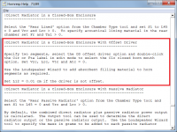
See the 'Direct Radiator in a closed-Box Enclosure With Offset Driver' entry in the Loudspeaker Models section of the Help file for details. Attachment 1 refers.
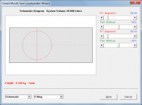
The easiest way to specify a 'closed box with offset driver' is to use the the Input Wizard to generate a representative example, and to then change the input parameter values to suit the actual design. The Input Wizard is accessed from under the main input parameters window Help menu. Attachment 2 refers.
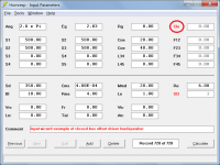
The input parameter values for the Input Wizard representative example are shown in Attachment 3. Note that the Clo 'closed horn mouth' option (circled in red) has been specified.
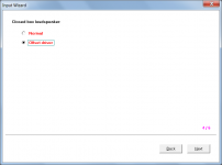
If required, absorbent filling material can be added to the enclosure using the Loudspeaker Wizard, as shown in Attachment 4.
The driver is mounted in the middle of the baffle on one axis, but not on the other. To illustrate, in Attachment 4 the driver is centred on the vertical Y-axis but offset on the horizontal X-axis.
Kind regards,
David
I have looked and I cannot find WHAT a closed box with offset driver enclosure is.
See the 'Direct Radiator in a closed-Box Enclosure With Offset Driver' entry in the Loudspeaker Models section of the Help file for details. Attachment 1 refers.
The easiest way to specify a 'closed box with offset driver' is to use the the Input Wizard to generate a representative example, and to then change the input parameter values to suit the actual design. The Input Wizard is accessed from under the main input parameters window Help menu. Attachment 2 refers.
The input parameter values for the Input Wizard representative example are shown in Attachment 3. Note that the Clo 'closed horn mouth' option (circled in red) has been specified.
If required, absorbent filling material can be added to the enclosure using the Loudspeaker Wizard, as shown in Attachment 4.
I assumed it was simply a closed box with the driver not mounted in the middle of the baffle
The driver is mounted in the middle of the baffle on one axis, but not on the other. To illustrate, in Attachment 4 the driver is centred on the vertical Y-axis but offset on the horizontal X-axis.
Kind regards,
David
Attachments
Hi All
I did measurements with the bass closed sub after putting a shelf filter on, it does up the respons so 20 hz fall into the whole respons, nabure not happy, because the measurement did rattle his stuff in the kitchen, but have a good relationship and he loves house, so was curieus about what I did.
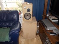
The box and the old phillips with a tweeter do like good, hoever the dips in the bass, I think these are room modes or maybe the placement as it is not good between couche and tv, maybe it need open in the middle, can make a table from it for example..
Now I go build the dipole and measure together to see if it does cardioid the solution for room modes?
For the bass, I go build me a class D bass amplifier with a shelf into it, now it is on a hybrid amp open loop.
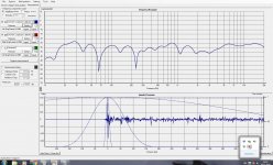
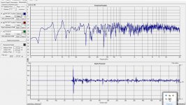
The last respons you can soo on pic 4 these is raw measurement.
have a nice day.
kees
I did measurements with the bass closed sub after putting a shelf filter on, it does up the respons so 20 hz fall into the whole respons, nabure not happy, because the measurement did rattle his stuff in the kitchen, but have a good relationship and he loves house, so was curieus about what I did.
The box and the old phillips with a tweeter do like good, hoever the dips in the bass, I think these are room modes or maybe the placement as it is not good between couche and tv, maybe it need open in the middle, can make a table from it for example..
Now I go build the dipole and measure together to see if it does cardioid the solution for room modes?
For the bass, I go build me a class D bass amplifier with a shelf into it, now it is on a hybrid amp open loop.
The last respons you can soo on pic 4 these is raw measurement.
have a nice day.
kees
Attachments
Last edited:
Hi Guys
I'm having a bit of trouble getting my hornresp frequency response graph to match reality closely enough to make design decisions on a project I'm starting. I am trying to simulate a block of 4 punishers sitting on the ground, not next to a wall. Punisher plan is here Punisher Horn MKII
I know from measuring my system with smarrt multiple times that the punishers roll-off at about 40hz. The sim is showing the roll-off at closer to 55hz.
I have tried simming the punishers as both OD and ND but it makes little difference.
I had a quick look at the sim. It doesn't seem to be an accurate representation of the actual horn layout. I'm not sure that it could be accurately simmed in Hornresp either. I'm also not sure why they reduced the expansion rate at the bottom of the horn then increased it towards the mouth either. All in all, it doesn't seem to be well optimized layout.
Did you take an impedance curve measurement of a built version of this horn? Compare that to the sim'd impedance curve to see if your Hornresp sim is a good match for the build. The impedance peaks won't be as high, but the dips should occur at the same frequencies.
I'm also not sure why they reduced the expansion rate at the bottom of the horn then increased it towards the mouth either. All in all, it doesn't seem to be well optimized layout.
I can see the modeler using similar principles to a port with flared ends.
I remember when someone posted instructions on how to double fold a TH. In 1 of the corners, the flare decreases and increases again. I ran across the situation when I built my negative flare TH. Apparently, the situation does not cause a problem between a modeled and measured response.
- Home
- Loudspeakers
- Subwoofers
- Hornresp