Hi Berd,
Not via diyAudio, but through the Hornresp download web page") .
.
Many thanks for posting the files - they have enabled me to quickly find the problems.
FIX 1
Move file 2441_225Hz_Lec.txt from your Drivers folder to your Import folder. It is actually a record file, not a driver file. Somehow it ended up in the wrong folder.
FIX 2
Remove the single blank space from the right hand side of the record 2 comment (B&C 10NW76 ).
(The blank space is actually a special non-visible character flag added at the end of the driver name, and is used by Hornresp when inserting a pasted driver name in front of an existing comment. It is at the end of your record 2 comment because at some time you have edited the comment field to leave only the pasted driver name. To avoid problems the hidden flag at the end of the name also needs to be removed, or alternatively, additional text added after the blank space. The important thing is that the special flag cannot be the last character in the comment field).
Make the above two changes, and I think you will then find that everything works as it should.
Kind regards,
David
I tried to send you a PM but it said you were not accepting messages
Not via diyAudio, but through the Hornresp download web page
.The "post crash" hornresp.dat file you requested in in the attached hornresp.zip file
I also attached all the problem driver files in the problem driver files.zip
Many thanks for posting the files - they have enabled me to quickly find the problems.
FIX 1
Move file 2441_225Hz_Lec.txt from your Drivers folder to your Import folder. It is actually a record file, not a driver file. Somehow it ended up in the wrong folder
.FIX 2
Remove the single blank space from the right hand side of the record 2 comment (B&C 10NW76 ).
(The blank space is actually a special non-visible character flag added at the end of the driver name, and is used by Hornresp when inserting a pasted driver name in front of an existing comment. It is at the end of your record 2 comment because at some time you have edited the comment field to leave only the pasted driver name. To avoid problems the hidden flag at the end of the name also needs to be removed, or alternatively, additional text added after the blank space. The important thing is that the special flag cannot be the last character in the comment field).
Make the above two changes, and I think you will then find that everything works as it should.
Kind regards,
David
Attachments
Hi Damien,
Let's keep it that way.
The amount of work involved would be MASSIVE!
It's not going to happen.
Kind regards,
David
It's only a idea
Let's keep it that way
.The amount of work involved would be MASSIVE!
It's not going to happen
.Kind regards,
David
I'd assume it would also be overwhelming to add a sidebranch absorber chamber feature "somewhere" to hornresp ?
Hi Fred,
You assume correctly
.Unfortunately it would require just as much work to implement as the stub feature requested by Damien.
Kind regards,
David
Hi,
Actually, segments are expending 360° in the 3third dimension we don't see. David, do you feel that sim still realistic for "flat" stub we can do in hornresp as really big but really short chamber ?
If so, that would mean that flat chamber/360° stub seems to gives the lowest resonnance for bandpass.
I imagine that how it is implemented, formulas used are 2d and so cannot be tweaked to set this 3rd dimension expansion to for example 0°, as stub. Do it ?
Last edited:
David, do you feel that sim still realistic for "flat" stub we can do in hornresp as really big but really short chamber ?
Hi Damien,
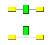
As shown in the attachment, the two topologies are quite different. In the first case the green "stub" chamber is in series with the yellow segments, whereas in the second case it is on a separate side branch. The sound pressures and volume velocities through the two systems will be different because of this.
I don't know where it will lead, but I am currently looking to see if it might be possible to implement your requested stub feature using a completely different method to the one you proposed. If I can get it to work, then I think that it should also be possible to specify a "sidebranch absorber chamber" rather than a standard stub, if so required, as requested by Fred.
The amount of work involved would still be massive (now lowercase), but no longer MASSIVE. It would take quite some time to implement - my best guess at this stage is several weeks at least...
If it turns out to be all too difficult, I will let you know, in due course.
Kind regards,
David
Attachments
David, when you are engaged and intrigued, things happen really fast.
If you keep improving the the hornresp, at a certain point it will used for other applications than sound.
The parallel "STUB" think is very close what they used in the intake system from engines at car applications. The intake length is tuned considering some resonances in order to increase air pressure at specific speed so it will increase engine torque. Longer pipes are good to improve toque at low speeds, while low tubes are good to improve power, you can't have both, the closes possible is reached when using variable intake system so the length is adjustable regarding engine speed Just a curiosity
If you keep improving the the hornresp, at a certain point it will used for other applications than sound.
The parallel "STUB" think is very close what they used in the intake system from engines at car applications. The intake length is tuned considering some resonances in order to increase air pressure at specific speed so it will increase engine torque. Longer pipes are good to improve toque at low speeds, while low tubes are good to improve power, you can't have both, the closes possible is reached when using variable intake system so the length is adjustable regarding engine speed
Just a curiositythe closes possible is reached when using variable intake system so the length is adjustable regarding engine speed
Hi Marcelo,
Just what we need - loudspeakers with acoustic stubs that vary in length as the frequency changes
.Kind regards,
David
Hi Marcelo,
Just what we need - loudspeakers with acoustic stubs that vary in length as the frequency changes
Kind regards,
David
I believe that is called a slide whistle
David, when you are engaged and intrigued, things happen really fast.
If you keep improving the the hornresp, at a certain point it will used for other applications than sound.
The parallel "STUB" think is very close what they used in the intake system from engines at car applications. The intake length is tuned considering some resonances in order to increase air pressure at specific speed so it will increase engine torque. Longer pipes are good to improve toque at low speeds, while low tubes are good to improve power, you can't have both, the closes possible is reached when using variable intake system so the length is adjustable regarding engine speed
That is exactly what F1 and IndyCar engines do! I think MotoGP uses variable intakes too.
That is exactly what F1 and IndyCar engines do! I think MotoGP uses variable intakes too.
Yep. Penny whistles Rule!
Sure, as long as you promise to play only one frequency at a time through your speakers.linear actuators anyone....?
Driver front volume tool question
I apologize if this has been covered in another post.
I did several searches and could not find it.
I have a question on the front volume tool and how it relates to the throat chamber volume (Vtc).
I found one post where David said the program considers the front driver volume but it was unclear how it considers it.
Essentially the question is:
Does the program automatically add the driver front volume or is the driver front volume tool a calculator only ?
Another way of asking this: Do I need to add the the driver front volume to Vtc manually or does hornresp do it for me ?
Example:
- A front loaded horn with a sealed rear chamber, i.e. no throat adapter.
- The driver is mounted directly to a mounting plate perpendicular to the axis of the horn.
- An 8" driver with Sd=522.
- A square throat in the adapter which is 3/4" (22 mm) thick plywood, e.g. Atc = 144 cm^2
- The driver front volume tool yields a front volume of 3023 cm^3
Question: When entering the Vtc, should the value be:
a) Atc * thickness of the plywood (144*2.2) = 316 cm^3; or
b) The driver front volume plus Atc * thickness of the plywood, (3023.78 + 316 = 3339.78 cm^3
I would conclude that a) means Hornresp considers the driver front volume for me and b) means I need to use the front driver tool and then add that volume manually
David noted the throat chamber acts as a low pass filter and I do see significant differences in the high end roll off of the simulation when entering a Vtc of 316 versus 3340.
The results would seems to indicate that consideration the driver front volume is pretty critical when doing the design.
On a loosely related note:
The program gives a warning when Atc is < Sd
This seems a bit counter intuitive to me for a front loaded horn because you want a compression ratio greater than one .
It seems like Atc would always be less than Sd, e.g. 144 < 522
Thanks much.
Hi Berd,
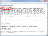
The Driver Front Volume tool is a calculator only.
You are not the first person to have asked this question, and in an attempt to clarify things the Help file was changed in the last release (quite coincidentally) to describe the calculator as a "stand-alone tool" - Attachment 1 refers.
You need to manually add the driver front volume to Vtc.
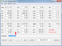
Normally Atc is not less than Sd. The compression ratio is given by Sd / S1, not Sd / Atc. Moving the mouse pointer over S1 or Sd shows the compression ratio in the status bar panel at the bottom of the Input Parameters window - Attachment 2 refers.
Incidentally, were you able to resolve the driver data base problem you were experiencing?
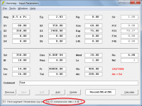
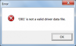
Changes will be made in the next release to automatically detect and remove any special non-visible character flag inadvertently left at the end of a record comment, and to also detect non-driver records in the Drivers folder - Attachment 3 refers. These two changes will hopefully prevent fatal errors similar to those you experienced, from being generated in the future.
Kind regards,
David
Does the program automatically add the driver front volume or is the driver front volume tool a calculator only ?
The Driver Front Volume tool is a calculator only.
You are not the first person to have asked this question, and in an attempt to clarify things the Help file was changed in the last release (quite coincidentally) to describe the calculator as a "stand-alone tool" - Attachment 1 refers.
Do I need to add the driver front volume to Vtc manually or does hornresp do it for me ?
You need to manually add the driver front volume to Vtc.
On a loosely related note:
The program gives a warning when Atc is < Sd
This seems a bit counter intuitive to me for a front loaded horn because you want a compression ratio greater than one .
It seems like Atc would always be less than Sd, e.g. 144 < 522
Normally Atc is not less than Sd. The compression ratio is given by Sd / S1, not Sd / Atc. Moving the mouse pointer over S1 or Sd shows the compression ratio in the status bar panel at the bottom of the Input Parameters window - Attachment 2 refers.
Incidentally, were you able to resolve the driver data base problem you were experiencing?
Changes will be made in the next release to automatically detect and remove any special non-visible character flag inadvertently left at the end of a record comment, and to also detect non-driver records in the Drivers folder - Attachment 3 refers. These two changes will hopefully prevent fatal errors similar to those you experienced, from being generated in the future.
Kind regards,
David
Attachments
David:
Thank you for the reply and for the assistance on my earlier issue.
Yes, you identified the problem and once I fixed it all is working perfectly.
I had moved the help file into a Word Doc to make it easier to search.
I looked but did not see anything.
I'll update the help file with the latest one and keep it current going forward.
Best Regards,
Berd
Last edited:
Throat adapter / Throat chamber calcs
David:
In thinking a bit more about Vtc (and Ltc) I became a bit confused.
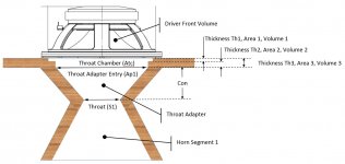
I created the attached sketch to hopefully bring some additional clarity for myself and others.
Please let me know if the labels in the attached are correct for the terms used on the input parameter screen.
I also added a couple of other labels just to make the discussion a bit easier.
Are the following equations correct ?
- Vtc = Driver Front Volume + Volume 1 + Volume 2
- Atc = (Area 1 *Thickness 1 + Area 2 * Thickness 2)/Thickness 3, i.e. the average area in Thickness 3
- Ltc = Vtc /Atc
The Ltc calculation is the one that has me perplexed.
The Driver Front Volume is typically much larger that Volume 1 + Volume 2
This in turn means that Ltc is much larger than thickness 3.
Should one be calculating the average area of the Driver Front Volume and be adding it into the Atc value ?
Should one just ignore Ltc as it relates to Thickness 3 ?
Thank you for all the support !
Best Regards,
Berd
David:
In thinking a bit more about Vtc (and Ltc) I became a bit confused.
I created the attached sketch to hopefully bring some additional clarity for myself and others.
Please let me know if the labels in the attached are correct for the terms used on the input parameter screen.
I also added a couple of other labels just to make the discussion a bit easier.
Are the following equations correct ?
- Vtc = Driver Front Volume + Volume 1 + Volume 2
- Atc = (Area 1 *Thickness 1 + Area 2 * Thickness 2)/Thickness 3, i.e. the average area in Thickness 3
- Ltc = Vtc /Atc
The Ltc calculation is the one that has me perplexed.
The Driver Front Volume is typically much larger that Volume 1 + Volume 2
This in turn means that Ltc is much larger than thickness 3.
Should one be calculating the average area of the Driver Front Volume and be adding it into the Atc value ?
Should one just ignore Ltc as it relates to Thickness 3 ?
Thank you for all the support !
Best Regards,
Berd
Attachments
Just a minor suggestion that might be easy to implement: if a user opens Hornresp and it prompts him to download a newer version, if the user selects to download the newer version, have Hornresp close after it passes the download link to a browser. That's because when the user downloads the newer version and tries to install it, the install will fail if the hornresp.exe file is already open.
Hi Berd,
Excellent.
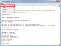
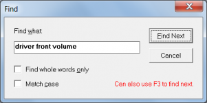
It should not be necessary to do that. The Help file has its own in-built search tool - see attachments.
Kind regards,
David
Yes, you identified the problem and once I fixed it all is working perfectly.
Excellent
.I had moved the help file into a Word Doc to make it easier to search.
It should not be necessary to do that. The Help file has its own in-built search tool - see attachments.
Kind regards,
David
Attachments
Are the following equations correct ?
- Vtc = Driver Front Volume + Volume 1 + Volume 2
- Atc = (Area 1 *Thickness 1 + Area 2 * Thickness 2)/Thickness 3, i.e. the average area in Thickness 3
- Ltc = Vtc /Atc
Hi Berd,
Your Vtc and Ltc equations are correct, and your Atc equation is certainly one way of calculating the throat chamber cross-sectional area.
The critical parameter value to get right is Vtc, which is why the Driver Front Volume tool was added originally - to make it easier for users to more accurately determine the required throat chamber value.
If the 'resonances masked' option is selected, then it doesn't matter what value is specified for Atc as the results won't change. If the 'resonances not masked' option is selected and a relatively small value is specified for Atc, then Ltc may become large enough for chamber resonances to be seen in the response. It is really a judgement call on the part of the user as to what assumptions to make when determining the value of Atc. This is why the parameter is described in Hornresp as the throat chamber "average" cross-sectional area.
In most cases I just set Atc equal to Sd, or for n multiple drivers, to n x Sd. Usually I find that this "rule of thumb" approach is close enough.
Kind regards,
David
- Home
- Loudspeakers
- Subwoofers
- Hornresp