I use Hornresp almost daily. Just not all the bells and whistlesMe too! I can't remember the last time I launched HR. I hate that I lost the ability to update the program on my work laptop again.

Me too! I can't remember the last time I launched HR. I hate that I lost the ability to update the program on my work laptop again.
I run it out of my personal OneDrive...
Hi David:
What, pray tell, is the radius flare profile? Can I use it to model a roundover on the through hole for a rear-mounted driver? I'm trying to do this but getting various error messages that make me realize I don't understand its definition or usage model. Neither the HR help nor google are helping.
Thanks,
Jack
What, pray tell, is the radius flare profile? Can I use it to model a roundover on the through hole for a rear-mounted driver?
Hi Jack,
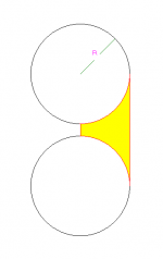
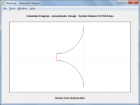
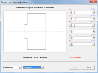
The axisymmetric radius flare horn profile is generated as shown in Attachment 1. The resultant horn is shown in Attachment 2. The example provided has a centre-subtended arc angle of 90 degrees, but the arc radius can be larger than that shown and the arc angle less, if required.
The 'Rad' flare option is offered as an alternative to the tractrix and spherical wave horn profiles.
The model is not suitable for the application you have in mind, and a "Horn too short" warning message will be generated in that case.
Kind regards,
David
Attachments
Thanks, David
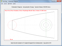
Can I see the input params screen? That looks suspiciously like what I want to model with S1 equal to the area of the panel through hole and R equal to its thickness - but when I try to create the 2nd picture in HR, I get the "horn too short" warning. Should not R equal L12?
Can I see the input params screen? That looks suspiciously like what I want to model with S1 equal to the area of the panel through hole and R equal to its thickness - but when I try to create the 2nd picture in HR, I get the "horn too short" warning. Should not R equal L12?
Hi Jack,
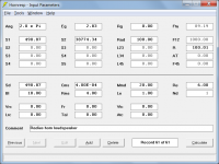
A screenprint of the Input Parameters window is attached. The way that the model works, it is not possible for R to be exactly equal to L12 - it must always be larger, although the difference can be as small as 0.1 mm, as shown in the test example.
As previously advised, the model is not suitable for the application you have in mind. If you attempt to use the radius flare profile with a relatively small L12 compared to the throat diameter, a "Horn too short" error message will be generated. This is because the model becomes invalid and the results inaccurate, under such "extreme" conditions.
Kind regards,
David
Attachments
Thanks.
I tried making L12 epsilon larger and scaling the whole thing up a factor of 10 but I didn't try changing the ratio of L12 to R ...
I guess when the horn is that short its not a horn, except perhaps at HF which is where I see an effect in the lab. I wonder if Axidriver has the same accuracy issue, will try.
This driver (Fountek FR58EX) really wants to be rear mounted from a mechanical point of view but the response seems worse that way.
Jack
Hi Jack,
As far as Hornresp is concerned, it is too short to be simulated as a horn. Even at high frequencies, because the throat area is relatively large compared to the mouth size, the horn loading effect will be minimal. The effect you are seeing in the lab is probably due to baffle edge diffraction.
Because AxiDriver uses the Boundary Element Method (BEM) in its simulations, it does not have the same accuracy issues as Hornresp.
Kind regards,
David
I guess when the horn is that short its not a horn, except perhaps at HF which is where I see an effect in the lab.
As far as Hornresp is concerned, it is too short to be simulated as a horn. Even at high frequencies, because the throat area is relatively large compared to the mouth size, the horn loading effect will be minimal. The effect you are seeing in the lab is probably due to baffle edge diffraction.
I wonder if Axidriver has the same accuracy issue, will try.
Because AxiDriver uses the Boundary Element Method (BEM) in its simulations, it does not have the same accuracy issues as Hornresp.
Kind regards,
David
Hi Jack,
As far as Hornresp is concerned, it is too short to be simulated as a horn. Even at high frequencies, because the throat area is relatively large compared to the mouth size, the horn loading effect will be minimal. The effect you are seeing in the lab is probably due to baffle edge diffraction.
Because AxiDriver uses the Boundary Element Method (BEM) in its simulations, it does not have the same accuracy issues as Hornresp.
Kind regards,
David
I'm sure you are right re' baffle diffraction, perhaps also a little bit of mouth reflection in the top octave. Nevertheless I had persisted out of general interest and found that HR allowed me to get within a factor of within between 2 and 3 of my target dimensions before it acknowledged its limitations (Clint Eastwood/Dirty Harry would approve). In fact the first thing I thought of when I saw the schematic was that I should extend the horn .01 cm to model a baffle but found that you don't allow that. Well, on to Axidriver or perhaps bow to the inevitable and design for front flush mount, which will require two sided milling to provide clearance for the terminals in back and to provide breathing room for the backwave.
Jack
Attachments
Hi Jack,
As far as Hornresp is concerned, it is too short to be simulated as a horn. Even at high frequencies, because the throat area is relatively large compared to the mouth size, the horn loading effect will be minimal. The effect you are seeing in the lab is probably due to baffle edge diffraction.
Because AxiDriver uses the Boundary Element Method (BEM) in its simulations, it does not have the same accuracy issues as Hornresp.
Kind regards,
David
For what it is worth I have found the math behind Hornresp to be accurate enough to forego jumping into the intensive calculations required by some fancy programs. Every simulation has it's limitations. As does every measurement tool. It's knowing and understanding them that is the key to their utility.
I have used this program for near twenty years. It's never really let me down that badly. and it keeps getting better. Thanks for your hard work David. From punch cards and text only print out to what we have now is pretty awesome when I think about it.
Its no reflection on HR that it can't do what I want in this case. The only criticism I would have, and its not really a criticism, is that it makes the things that it can do so easy that we become spolied - loath to use the BEM/FEM tools that require so much more effort. Axidriver is somewhat in between once you spend a few minutes creating a spreadsheet to make a staircase approximation to your flare, the rest is also easy.
Its no reflection on HR that it can't do what I want in this case. The only criticism I would have, and its not really a criticism, is that it makes the things that it can do so easy that we become spolied - loath to use the BEM/FEM tools that require so much more effort. Axidriver is somewhat in between once you spend a few minutes creating a spreadsheet to make a staircase approximation to your flare, the rest is also easy.
I just looked up Axidriver. Joerg has been busy!
Didn't know about this program. I will have to investigate.
Thanks!
Hello all.
I have been working with Hornsrep pretty intensely over the last week trying to figure it out. I have made progress but feel like I have hit a wall that I could use some help getting over.
For one this might just be a bad idea so please feel free to stop me before the sawdust starts flying, I will take no offence
What in short I would like to end up with is more or less (deep breath) a 10 cm full range driver in a vented enclosure, front loaded with a two stage conical-parabolic horn that goes down to about 200 Hz. Approx 100 cm long.
I did read the manual as best as I could but I am still feeling very unsure about my results. I have used the input wizard and selected the Tapped Horn option. Then as per the manual zeroed out the Vrc, Lrc, Ap and Lpt. and gone and set L12 to .01 because as far as I understand in my situation the driver is not offset. It is right in the mouth. I guess I just don't understand how these settings account for the enclosure. As far as I can tell by doing this you would be completely removing the enclosure. Is this not so? Am I missing something?
This is pretty much all I have fund to explain it in there but there is a good chance that I am missing what I need to see.
"A horn-loaded vented-box enclosure can now
be specified with the port exit located inside the horn mouth.
Select the tapped horn option and set Vrc, Lrc, Ap and Lpt >
0, with L12 = 0.01 cm if the driver is not offset."
Assuming that this is not an entirely bad idea it makes sense that venting into the horn might not cause to many issues as long as the frequency of the port/enclosure was considerably lower than the lowest frequency of the horn. This would be the case in my situation. I am aiming for around 70hz. This is based pretty much entirely on a gut feeling and 25 years of working with sound, no math here though.
I don't have a strong understanding of pressure dynamics inside the throat of the horn. And I understand it even less when trying to use the same driver to re-enforce itself at selective frequencies in a horn. My gut tells me that having any type of hole in the early stages of the horn would be a bad idea. Seems like it would be safer further down the line where the pressure in the horn is lower.
Any help would be greatly appreciated I fear I am starting to burn out. Just need a little more peace of mind before I start chopping up sheets of wood
Then as per the manual zeroed out the Vrc, Lrc, Ap and Lpt. and gone and set L12 to .01 because as far as I understand in my situation the driver is not offset. It is right in the mouth. I guess I just don't understand how these settings account for the enclosure. As far as I can tell by doing this you would be completely removing the enclosure. Is this not so? Am I missing something?
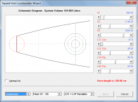
Hi Sugar Lion,
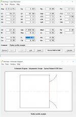
Just to clarify, the Hornresp Help file says to set Vrc, Lrc, Ap and Lpt to values greater than zero (> 0), not equal to zero (= 0). Vrc and Lrc specify the enclosure, and Ap and Lpt specify the port tube from the enclosure into the horn near the mouth.
Also, by setting L12 = 0.01 cm (or to 0.10 cm in the Loudspeaker Wizard) the driver is located at the throat, not "right in the mouth".
The attachments show the system arrangement I think you are looking for (not to scale).
Kind regards,
David
Attachments


Hi Sugar Lion,
Just to clarify, the Hornresp Help file says to set Vrc, Lrc, Ap and Lpt to values greater than zero (> 0), not equal to zero (= 0). Vrc and Lrc specify the enclosure, and Ap and Lpt specify the port tube from the enclosure into the horn near the mouth.
My goodness I totally did not read that correctly. Thank you so much for pointing this out!
Also, by setting L12 = 0.01 cm (or to 0.10 cm in the Loudspeaker Wizard) the driver is located at the throat, not "right in the mouth".
Sorry that was a wrong choice of words on my part. A symptom of late night sleepy posting. I did indeed mean to say in the throat.
The attachments show the system arrangement I think you are looking for (not to scale).
Kind regards,
David
Well holly jumping Sugar Lions! Thank you so much for these rather encouraging and clarifying images. This post has put wind in my sails!
I will run through different setups in Hornsrep today but I was wondering if you could let me know what you think about venting into the horn closer to the throat or even in the front chamber. Is this generally just best avoided?
Again thank you so much for your input and help. And while I am at it for the program!
I run it out of my personal OneDrive...
Thanks guy! I was able to download version 48.50 to OneDrive on my work laptop.
- Home
- Loudspeakers
- Subwoofers
- Hornresp