...
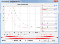
1/f and Claus Futtrup guideline limits can now be added to the loudspeaker and filter wizard group delay charts.
...
THANK YOU!
")
It is a big advantage to have some comparison lines for group delay.
I really appreciate your effort in making this wonderful program!
Link to some background info:
http://www.cfuttrup.com/Book_05_Futtrup.pdf
Hornresp Update 4520-180616
Hi Everyone,
The following bugs have now been fixed.
BUG 1
The timer mouse pointer would stay on after the loudspeaker wizard group delay chart was double-clicked, if absorbent filling material had been specified.
BUG 2
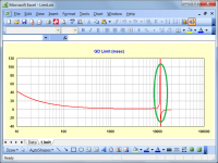
The separating line below the loudspeaker wizard group delay chart was being hidden when a limit line was added - see attachment.
Kind regards,
David
Hi Everyone,
The following bugs have now been fixed.
BUG 1
The timer mouse pointer would stay on after the loudspeaker wizard group delay chart was double-clicked, if absorbent filling material had been specified.
BUG 2
The separating line below the loudspeaker wizard group delay chart was being hidden when a limit line was added - see attachment.
Kind regards,
David
Attachments
Hornresp Update 4520-180621
Hi Everyone,
CHANGE 1
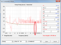
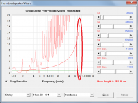
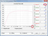
The maximum frequency of the 1/f and Claus Futtrup group delay limit guidelines has been increased from 2000 Hz to 8000 Hz. It is not practical to extend the upper frequency beyond 8000 Hz because the Claus Futtrup expression starts to break down and produce erroneous results above that frequency. Attachments 1 to 3 refer.
CHANGE 2
With the 1 - 2000 Hz frequency range selected, and acoustical filling material specified, the loudspeaker wizard chart frequency scale can now be switched from 1 - 200 Hz to 10 - 2000 Hz if required. Previously this was not possible. Attachment 4 refers
Kind regards,
David
Hi Everyone,
CHANGE 1
The maximum frequency of the 1/f and Claus Futtrup group delay limit guidelines has been increased from 2000 Hz to 8000 Hz. It is not practical to extend the upper frequency beyond 8000 Hz because the Claus Futtrup expression starts to break down and produce erroneous results above that frequency. Attachments 1 to 3 refer.
CHANGE 2
With the 1 - 2000 Hz frequency range selected, and acoustical filling material specified, the loudspeaker wizard chart frequency scale can now be switched from 1 - 200 Hz to 10 - 2000 Hz if required. Previously this was not possible. Attachment 4 refers
Kind regards,
David
Attachments
CHANGE 2
the loudspeaker wizard chart frequency scale can now be switched from 1 - 200 Hz to 10 - 2000 Hz if required. Previously this was not possible. Attachment 4 refers
Kind regards,
David
My fault. I was expecting to see the 1-200hz screenshot too.
Last edited:
Hi Mark,
I fear that your memory is starting to go - you must be working too hard.
Semi-inductance and frequency-dependent damping options were added to the driver model in Version 43.00, which you definitely saw.
http://www.diyaudio.com/forums/subwoofers/119854-hornresp-821.html#post5405237
Kind regards,
David
I fear that your memory is starting to go - you must be working too hard
.Semi-inductance and frequency-dependent damping options were added to the driver model in Version 43.00, which you definitely saw
.http://www.diyaudio.com/forums/subwoofers/119854-hornresp-821.html#post5405237
Kind regards,
David
Hi freddi,
Try removing the segment 4 mouth area S5 value of 8.00. Hopefully this will fix the problem.
The segment 3 mouth area S4 value of 437.00 should have been automatically copied down as the segment 4 throat area S4 when 8.00 was entered into S5. I have no idea why this did not happen. Please let me know if you still have a problem.
Kind regards,
David
Hi freddi,
Further to my post above, I now suspect that the segment 3 mouth area S4 value of 437.00 was indeed automatically copied down as the segment 4 throat area S4 when 8.00 was entered into S5, but that you probably subsequently deleted the 437.00 value from segment 4 for some reason, leaving just the 8.00 value, which triggered the error message.
Kind regards,
David
Hi Mark,
I fear that your memory is starting to go - you must be working too hard
Semi-inductance and frequency-dependent damping options were added to the driver model in Version 43.00, which you definitely saw
http://www.diyaudio.com/forums/subwoofers/119854-hornresp-821.html#post5405237
Kind regards,
David
I blame to much sun on my little bean.
Yes it is most definitely already done!
And yes I have been working a little bit more as of late. Every time I turn Hornresp on you have another update. So right back at you on the really working hard front. The improvements are significant. Not just simulation aids and tweaks but actual improvements to the quality of the simulations.
So now this leads me to ask if the lossy Le button still has relevance? Or are you incorporating the semi-inductance model throughout all of the Hornresp calculations? I'll be going to China this fall for a few jobs and at one of them I plan on showing off this little program. I'm pretty sure that question will come up. Some pretty sharp tools in that shed.
So now this leads me to ask if the lossy Le button still has relevance?
The "lossy Le" option can be of some value when the values of the extra parameters required for the semi-inductance model are not available.
The "lossy Le" option can be of some value when the values of the extra parameters required for the semi-inductance model are not available.
In other words VERY often.
In other words VERY often.
Well, they should be fairly easy to obtain, if you take the steps to obtain them when doing t/s parameter measurement
. While DATS can't currently measure those parameters directly, it should be possible to export the impedance curves from DATS into REW and use REW to calculate them.
All that's needed are two impedance curves from the same driver, and the ones which will be generated by DATS as part of the t/s parameter measurement process can be used for this purpose.
The "lossy Le" option can be of some value when the values of the extra parameters required for the semi-inductance model are not available.
Good answer! Thanks Brian.
I should have thought a little bit more. We are not accustomed to entering the correct parameters for lossy inductance calculation as of yet.
In other words VERY often.
Hard to argue when you are right Josh!
Thanks.
Well, they should be fairly easy to obtain, if you take the steps to obtain them when doing t/s parameter measurement
While DATS can't currently measure those parameters directly, it should be possible to export the impedance curves from DATS into REW and use REW to calculate them.
All that's needed are two impedance curves from the same driver, and the ones which will be generated by DATS as part of the t/s parameter measurement process can be used for this purpose.
So now you are making me wonder if an FRD file import could be a new option for the generation of the correct Semi-Inductance model within Hornresp.
I noticed something interesting today. Using the passive filter wizard (sealed and ported boxes) it became clear that if the filter is not set about a decade or more above fs you get a horrible resonant peak in the mid bass region. One of the implications is that it is essentially impossible to use a 2.5 way arrangement for significant bass extension. Saved myself a lot of fiddling.
Unless of course a zobel might help...
Unless of course a zobel might help...
Hi Mark,
.
As Brian and Josh have indicated, the Lossy Le model can be useful when nothing better is available.
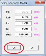
The semi-inductance model is incorporated into all Hornresp calculations, but is activated only when the user enters non-zero values for the advanced driver parameters Re', Leb, Le, Ke and Rss, and clicks the On button.
Kind regards,
David
I blame to much sun on my little bean.
.So now this leads me to ask if the lossy Le button still has relevance?
As Brian and Josh have indicated, the Lossy Le model can be useful when nothing better is available.
Or are you incorporating the semi-inductance model throughout all of the Hornresp calculations?
The semi-inductance model is incorporated into all Hornresp calculations, but is activated only when the user enters non-zero values for the advanced driver parameters Re', Leb, Le, Ke and Rss, and clicks the On button.
Kind regards,
David
Attachments
- Home
- Loudspeakers
- Subwoofers
- Hornresp