After some months of experiments I had to make some measurements of my ROAR12 design.


With 28,3 volts input Hornesp predicts 4,4 mm one way cone excursion without lossy LE and 5 mm one way cone excursion with lossy LE enabled.
I used the signal generator in REW and a Tamp E800 to drive my B&C 12PS100 with 28,3 volts over the speaker terminals. I lightly pushed the the backside of a pencil held between my hand and the speaker magnet, against the cone and slowly increased the volume to 28,3 volts. The cone pushed the pencil outwards until it stopped buzzing. I tried very gently several times to get the end of the pencil closer to the moving cone without any buzzing noise.
With this simple crude measurement I could measure the cone excursion to slightly less then 1,0 mm. I round this measurement upwards to 1,0 mm to not exaggerate the difference between the Hornresp sim and my real world results.
I have been playing sine wave sweeps from 20 Hz to 90 Hz and I could not find this hump in the cone excursion anywhere. The ROAR design really holds the cone very firmly.
It seems Hornresp exaggerates the predicted cone excursion by 440% (8,8/2 mm) at 53 Hz and 28,3 volts (100 watt in 8 ohms) in my ROAR design. The difference grows to 500% with the use of Lossy Le enabled in Hornresp.
We have been testing several different drivers in several variations of my TPQWR designs and we have seen this behavior over and over again.
Yesterday we pushed a cheap 500 watt (peak) car audio driver to 2000 watts in a TPQWR and we could not get more then 10 mm p-p cone excursion. Hornresp predicts close to 60 mm p-p cone excursion. We did not measure the spl but this cheap car audio 12 inch driver made everything inside a 1000 m2 store rattle and buzz with ease.
This is the reason I asked if Hornresp could factor in non-linear aspects of large "slugs" of air in large ducts earlier in this thread. This seems to be a prime example of the non-linear behavior at high sound pressure levels.
Cheers,
Johannes
After some months of experiments I had to make some measurements of my ROAR12 design.
Did you measure the impedance curve for your design? This should be the first step in trying to compare the results to a Hornresp sim. Typically the impedance peaks and dips should be close to or at the same frequencies in the Hornresp sim. The height of the peaks will be lower (Hornresp does not include the effect of box losses), and the position of the lowest impedance peak might be a bit different, but if the rest lines up, there's a pretty good chance that you've built what was sim'd.
As for excursion, it basically tracks the impedance curve. However, Hornresp assumes a flat BL curve (unlimited Xmax), so its predictions, particularly when excursion is approaching the driver's rated Xmax, should be taken with a grain of salt
") .
.Did you do any distortion measurements for your build?
and the position of the lowest impedance peak might be a bit different, but if the rest lines up, there's a pretty good chance that you've built what was sim'd.
I have not measured the impedance peaks, but it does not seem to have a large effect wherever the peaks are. There is no measurable peaks in the cone excursion at 28,3 volts over the terminals over 35 Hz. Below 35 Hz the cone excursion starts to increase slowly and below 25 Hz it increases fast.
Cheers,
Johannes
Hornresp Update 4240-180101
Hi Everyone,
BUG FIX
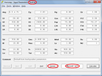
Further to post http://www.diyaudio.com/forums/full-range/315936-loaded-horn-design-3.html#post5287066, if a new data file was created by selecting the File > New menu while the Delete button on the Input Parameters window was enabled, the Delete button would remain enabled even though the newly-created file only contained a copy of the default record - see Attachment 1.
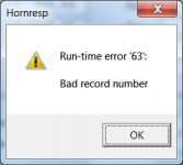
A fatal run-time error would be generated if the default record was then deleted by clicking the Delete button - see Attachment 2.
To ensure that this potential problem cannot occur, the Delete button is now always disabled following the creation of a new data file.
Kind regards,
David
Hi Everyone,
BUG FIX
Further to post http://www.diyaudio.com/forums/full-range/315936-loaded-horn-design-3.html#post5287066, if a new data file was created by selecting the File > New menu while the Delete button on the Input Parameters window was enabled, the Delete button would remain enabled even though the newly-created file only contained a copy of the default record - see Attachment 1.
A fatal run-time error would be generated if the default record was then deleted by clicking the Delete button - see Attachment 2.
To ensure that this potential problem cannot occur, the Delete button is now always disabled following the creation of a new data file.
Kind regards,
David
Attachments
It seems Hornresp exaggerates the predicted cone excursion by 440% (8,8/2 mm) at 53 Hz and 28,3 volts (100 watt in 8 ohms) in my ROAR design.
Hi Johannes,
"Small signal" driver parameter values are used in your ROAR design simulation. 28.3 volts is not a small input signal
.Back in 2008 Dr Bjørn Kolbrek showed quite conclusively using very accurate measurement techniques that when an appropriate input signal is used (in his case 2.83 volts rms), "the Hornresp predictions are very close to reality".
http://www.diyaudio.com/forums/subwoofers/119854-hornresp-15.html#post1591527
Kind regards,
David
Thank you David McBean!
Yes, I know Hornresp is very accurate at 1 watt aka small signal. I don't mean to criticize Hornresp in any way.
The reason I post this is to highlight the max spl prediction capability of Hornresp.
Usually it seems to be quite accurate and correct., but here it seems we have found a design that departs for this normal behavior in a very interesting way.
I find this discrepancy between Hornresp and my ROAR design very interesting. I am surprised by the stellar performance of the ROAR design at high power levels.
I do understand that I probably need to use COMSOL or something similar to properly simulate my ROAR design at high power levels. We are actually looking into this, but COMSOL has a quite steep learning gradient and a discouraging price tag.
Regards,
Johannes
Thank you David McBean!
Yes, I know Hornresp is very accurate at 1 watt aka small signal. I don't mean to criticize Hornresp in any way.
The reason I post this is to highlight the max spl prediction capability of Hornresp.
Usually it seems to be quite accurate and correct., but here it seems we have found a design that departs for this normal behavior in a very interesting way.
I find this discrepancy between Hornresp and my ROAR design very interesting. I am surprised by the stellar performance of the ROAR design at high power levels.
I do understand that I probably need to use COMSOL or something similar to properly simulate my ROAR design at high power levels. We are actually looking into this, but COMSOL has a quite steep learning gradient and a discouraging price tag.
Regards,
Johannes
Your observations are visual?
If they are visual at what frequencies are you doing the observations?
Below 50 hertz you will be able to see the movement easily.
And this might help you get an accurate idea of the movement.

As for excursion, it basically tracks the impedance curve. However, Hornresp assumes a flat BL curve (unlimited Xmax), so its predictions, particularly when excursion is approaching the driver's rated Xmax, should be taken with a grain of salt
Also keep in mind that driver suspensions are nonlinear and gets stiffer as excursion increases. One reason is to prevent the coil from leaving the gap.
Hornresp does not model driver nonlinearity, which can have quite a large effect on the performance at high power levels. Suspension nonlinearity, BL nonlinearity, increase in Re with temperature, modulation of Le etc means that the small signal parameters will not give a good representation of driver behaviour at high levels.
My guess is that the difference between simulated and measured performance is most likely due to the shift in driver parameters, rather than nonlinear acoustics.
Below 50 hertz you will be able to see the movement easily.
And this might help you get an accurate idea of the movement.
Thanks for a brilliantly simple and useful idea!
I will try this as soon as I can. I hope I can make a video of the cone excursion at 28,3 watts using this simple little measuring method.
Suspension nonlinearity, BL nonlinearity, increase in Re with temperature, modulation of Le etc means that the small signal parameters will not give a good representation of driver behaviour at high levels.
I don't believe a B&C 12PS100 has 7 dBs of power compression or Bl non-linearity at 100 watts. If so, it would be a very crappy driver for pro audio use. 28,3 volts into a nominal 8 ohm driver and 2 mm peak to peak cone excursion is not enough cone excursion to push a B&C 12PS100 into heavy suspension based mechanical limiting and compression or BL nonlinear compression.
I mention the cheap car audio driver and 2000 watts because I am impressed with the performance. This driver did show signs of thermal compression and BL nonlinearity, along with a bad smell of a red hot voice coil.
These measurements of cone excursion was done with my ROAR12 and my B&C 12PS100, not the cheap car audio driver.
Cheers,
Johannes
Last edited:
could you post some rew measurements or arta of this roar12 ?After some months of experiments I had to make some measurements of my ROAR12 design.
View attachment 653942
View attachment 653943
View attachment 653944
With 28,3 volts input Hornesp predicts 4,4 mm one way cone excursion without lossy LE and 5 mm one way cone excursion with lossy LE enabled.
I used the signal generator in REW and a Tamp E800 to drive my B&C 12PS100 with 28,3 volts over the speaker terminals. I lightly pushed the the backside of a pencil held between my hand and the speaker magnet, against the cone and slowly increased the volume to 28,3 volts. The cone pushed the pencil outwards until it stopped buzzing. I tried very gently several times to get the end of the pencil closer to the moving cone without any buzzing noise.
With this simple crude measurement I could measure the cone excursion to slightly less then 1,0 mm. I round this measurement upwards to 1,0 mm to not exaggerate the difference between the Hornresp sim and my real world results.
I have been playing sine wave sweeps from 20 Hz to 90 Hz and I could not find this hump in the cone excursion anywhere. The ROAR design really holds the cone very firmly.
It seems Hornresp exaggerates the predicted cone excursion by 440% (8,8/2 mm) at 53 Hz and 28,3 volts (100 watt in 8 ohms) in my ROAR design. The difference grows to 500% with the use of Lossy Le enabled in Hornresp.
We have been testing several different drivers in several variations of my TPQWR designs and we have seen this behavior over and over again.
Yesterday we pushed a cheap 500 watt (peak) car audio driver to 2000 watts in a TPQWR and we could not get more then 10 mm p-p cone excursion. Hornresp predicts close to 60 mm p-p cone excursion. We did not measure the spl but this cheap car audio 12 inch driver made everything inside a 1000 m2 store rattle and buzz with ease.
This is the reason I asked if Hornresp could factor in non-linear aspects of large "slugs" of air in large ducts earlier in this thread. This seems to be a prime example of the non-linear behavior at high sound pressure levels.
Cheers,
Johannes
Hi David:
A belated Happy New Year to you and to all my co-benefactees of your good work.
One of the things I find myself doing lately is generating a crossover target reference curve in one record and then capturing the result for later comparison when doing equalization in another record. An example target reference curve would be when you take a flat line frequency response curve and apply an LR4 low pass filter curve to it.
When I go back to the record of the driver/horn I'm simulating, I can then see how close my equalization has gotten me to that target reference. My primary goal is just to ascertain whether such a crossover is feasible but, having a touch of OCD, I would love to be able to display the captured result in the filter wizard window instead of the Baseline response so as to be able to see the target while tuning the filters. David: could/would you please add a checkbox option for displaying a captured FR in place of the baseline FR?
Another thing I do once in a while is change a horn from OD to ND and back so that HR can show me its directivity. The use case is developing a conical synergy. Were it not for the driver offset, one could see its directivity, provided one hadn't added a secondary flare. So I like to tweak the model for a quick look at the directivity. In order to get back where I started, I have to double click through all the driver options OD, TH, TH1, CH, ... ND. Anomalously, if I started with a rear lined chamber, when I complete the loop, I end up with a throat ported chamber. Needless to say, this caused a moment's panic and confusion the first time it happened. I have to remember to restore the chamber setting. I don't think this is a problem but it is a curiosity and it would be marginally better if the chamber setting wasn't affected by clicking through driver location options.
Another thing I'm doing is simulating slot loaded woofers that will be used in pairs . I have equalization in my simulations turned ON. When I engage the multiple speakers tool, it automatically turns equalization OFF. I go back to the wizard and turn it on and find, not unexpectedly that the filters need to be tweaked because having two identical speakers in close proximity alters their response. What one would like to do, if always using the speakers in pairs, is tune and preserve the equalization for MultipleSpeakers=2. The problem with this scenario is that MultipleSpeaker state isn't preserved when exiting the record. If I look at that record some time in the future, I'll find the EQ is not right and I might not remember that the reason is that the EQ was tuned with MultipleSpeakers=2. If I do remember it and turn MS on, then that turns EQ off and so I have to go back into the filter wizard and press the ON button before my OCD self is happy with the results.
I think part of the solution, if you view the above as a problem, is saving the multiple speakers setting whenever F9 is pressed in the filter wizard. If the multiple speakers setting is preserved in this way, then the state needs to be displayed, perhaps next to the red "Equalizer Filters", e.g. Equalizer Filters, MS=2".
Best regards,
Jack
could you post some rew measurements or arta of this roar12 ?
Agreed.
Impedance measurement and an unprocessed, unsmoothed close mic response would clarify a lot.
Thanks for a brilliantly simple and useful idea!
I will try this as soon as I can. I hope I can make a video of the cone excursion at 28,3 watts using this simple little measuring method.
Not my idea. But I appreciate it's use to.
This is a direct copy of a GIF from Siegfried Linkwitz. The S L on the drawing.
No matter who the idea comes from it is a great way to figure out cone movement in a low tech fashion.
Hi Jack,
Thanks - and a belated Happy New Year to you also.
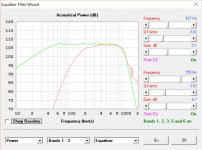
1. Press Ctrl+C when the Filter Wizard power or pressure response chart is displayed to capture the current results.
2. Press Ctrl+V to show or hide previously captured Filter Wizard results.
In Edit mode:
1. Double-click on the OD disabled text box (rather than the red OD label) to select the Driver Arrangement tool.
2. Select the Normal Nd arrangement from the drop-down list box.
3. Double-click on the ND label when ready to switch back to OD.
The chamber setting will not be affected.
The chamber setting automatically changes to prevent invalid combinations from being specified.
Nd and OD can have Fr+Tal, Ap+Lpt or Ap1+Lp
TH and TH1 can have Ap+Lpt or Ap1+Lp (but not Fr+Tal)
CH can have Ap1+Lp (but not Fr+Tal or Ap+Lpt)
While it may appear simple enough to implement, unfortunately it would significant changes to the way that things are done internally. It's not going to happen.
Kind regards,
David
A belated Happy New Year to you
Thanks - and a belated Happy New Year to you also
.I would love to be able to display the captured result in the filter wizard window instead of the Baseline response so as to be able to see the target while tuning the filters.
1. Press Ctrl+C when the Filter Wizard power or pressure response chart is displayed to capture the current results.
2. Press Ctrl+V to show or hide previously captured Filter Wizard results.
Another thing I do once in a while is change a horn from OD to ND and back so that HR can show me its directivity. The use case is developing a conical synergy. Were it not for the driver offset, one could see its directivity, provided one hadn't added a secondary flare. So I like to tweak the model for a quick look at the directivity. In order to get back where I started, I have to double click through all the driver options OD, TH, TH1, CH, ... ND. Anomalously, if I started with a rear lined chamber, when I complete the loop, I end up with a throat ported chamber. Needless to say, this caused a moment's panic and confusion the first time it happened. I have to remember to restore the chamber setting.
In Edit mode:
1. Double-click on the OD disabled text box (rather than the red OD label) to select the Driver Arrangement tool.
2. Select the Normal Nd arrangement from the drop-down list box.
3. Double-click on the ND label when ready to switch back to OD.
The chamber setting will not be affected.
it would be marginally better if the chamber setting wasn't affected by clicking through driver location options.
The chamber setting automatically changes to prevent invalid combinations from being specified.
Nd and OD can have Fr+Tal, Ap+Lpt or Ap1+Lp
TH and TH1 can have Ap+Lpt or Ap1+Lp (but not Fr+Tal)
CH can have Ap1+Lp (but not Fr+Tal or Ap+Lpt)
I think part of the solution, if you view the above as a problem, is saving the multiple speakers setting whenever F9 is pressed in the filter wizard. If the multiple speakers setting is preserved in this way, then the state needs to be displayed, perhaps next to the red "Equalizer Filters", e.g. Equalizer Filters, MS=2".
While it may appear simple enough to implement, unfortunately it would significant changes to the way that things are done internally. It's not going to happen
.Kind regards,
David
If I look at that record some time in the future, I'll find the EQ is not right and I might not remember that the reason is that the EQ was tuned with MultipleSpeakers=2.
Hi Jack,
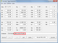
Just a thought - could you perhaps include a prompt in the Comment field to jog your memory in the future, as shown in the attached example for two speakers in parallel?
Kind regards,
David
Attachments
Last edited:
Correction
Should have read: "unfortunately it would require significant changes".
"unfortunately it would significant changes"
Should have read: "unfortunately it would require significant changes".
Should have read: "unfortunately it would require significant changes".
Thanks, David, I understand. Back when I had a day job, we had a complex ASIC product with a 15 year legacy that was regularly updated. We could add features readily but architectural changes literally took an extra year.
Hi Jack,
1. Press Ctrl+C when the Filter Wizard power or pressure response chart is displayed to capture the current results.
2. Press Ctrl+V to show or hide previously captured Filter Wizard results.
David
Awesome! I capture in the filter wizard of the reference record and display in the filter wizard of the design record and I can tell at a glance if I've got enough BW.
Thanks.
Jack
Attachments
When I engage the multiple speakers tool, it automatically turns equalization OFF.
If all goes according to plan, in the next release ON filter settings will remain ON when the Multiple Speakers tool is selected.
- Home
- Loudspeakers
- Subwoofers
- Hornresp