Unfortunately you cannot open the help when you are inside Loudspeaker Wizard. If you open the help before the wizard, you still cannot scroll the help file. So these questions end up here
Hi more10,
That's no excuse
.Simply export Hornresp Help as a text file using the File > Export menu command in Hornresp Help, and then open the exported file in Notepad, Word or similar.
If necessary, the font size can be increased in Notepad using Format > Font - see attachment.
Kind regards,
David
Attachments
I have found how to remove the stuffing, just type F9 and you see all the hidden stuff.
Excellent
.Hi Chris,
Further to Oliver's comment above - after pressing F9, note that you can then double-click on the Fr1 Segment 1 slider caption to change it to Fr1 Segment 2, etc.
Extract from the Hornresp Help file:
"Absorbent filling material can be included in the horn segments of a Loudspeaker Wizard system by selecting the Chamber option and then pressing the F9 function key to show or hide the Fr1 and Tal1 slider controls. The airflow resistivity of the absorbent filling material is specified in mks rayls/m using the Fr1 slider control.
Different airflow resistivity values can be specified for each segment. Double-click on the Fr1 slider caption to select a segment. If the Fr1 slider value is changed while the F5 function key is pressed, all segments are set to the same resistivity value."
Seems pretty clear to me.
Kind regards,
David
When in the Loudspeaker Wizard/chamber hit F9, seems to work just fine?
Further to Oliver's comment above - after pressing F9, note that you can then double-click on the Fr1 Segment 1 slider caption to change it to Fr1 Segment 2, etc.
Extract from the Hornresp Help file:
"Absorbent filling material can be included in the horn segments of a Loudspeaker Wizard system by selecting the Chamber option and then pressing the F9 function key to show or hide the Fr1 and Tal1 slider controls. The airflow resistivity of the absorbent filling material is specified in mks rayls/m using the Fr1 slider control.
Different airflow resistivity values can be specified for each segment. Double-click on the Fr1 slider caption to select a segment. If the Fr1 slider value is changed while the F5 function key is pressed, all segments are set to the same resistivity value."
Seems pretty clear to me
.Kind regards,
David
Originally Posted by David McBean
Seems pretty clear to me
I wonder if it has Anything to do with the fact you code it
Hornresp Update 3460-140509
Hi Everyone,
CHANGE 1
The Combined Response tool has been renamed the Output tool, the total system output is now the default response, and the selected output option is retained until a different record is chosen.
CHANGE 2
The SPL Response chart has been renamed the Acoustical Power chart (which becomes the Acoustical Pressure chart when the Directivity Response tool is used).
CHANGE 3
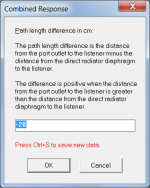
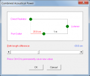
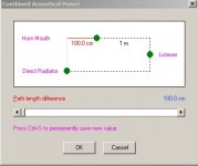
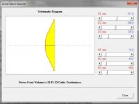
The path length difference input form has been changed. The positions of the two outputs relative to the listener are now shown in a schematic diagram, rather than being described in text. A text description has been retained in the Help file. Attachment 1 shows the old form, attachment 2 shows the new form.
CHANGE 4
The problem reported by Oliver in Post #4409 has been fixed.
Kind regards,
David
Hi Everyone,
CHANGE 1
The Combined Response tool has been renamed the Output tool, the total system output is now the default response, and the selected output option is retained until a different record is chosen.
CHANGE 2
The SPL Response chart has been renamed the Acoustical Power chart (which becomes the Acoustical Pressure chart when the Directivity Response tool is used).
CHANGE 3
The path length difference input form has been changed. The positions of the two outputs relative to the listener are now shown in a schematic diagram, rather than being described in text. A text description has been retained in the Help file. Attachment 1 shows the old form, attachment 2 shows the new form.
CHANGE 4
The problem reported by Oliver in Post #4409 has been fixed.
Kind regards,
David
Attachments
I wonder if it has Anything to do with the fact you code it
I guess that could have something to do with it
.Hi David,
We just cannot thank you enough.
Your newest Combined Acoustical Power window is just great, no more pondering what's closer.
Nice.
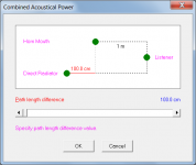
Just to be sure, the attached screen capture (+ 100.0 cm) means that the Horn Mouth is 2 m from the Listener, and the Direct Radiator is 1 m from the Listener?
Regards,
We just cannot thank you enough.
Your newest Combined Acoustical Power window is just great, no more pondering what's closer.
Nice.
Just to be sure, the attached screen capture (+ 100.0 cm) means that the Horn Mouth is 2 m from the Listener, and the Direct Radiator is 1 m from the Listener?
Regards,
Attachments

Hey all,
Trying to translate numbers in hornresp to an actual build.
The build im trying to achieve is something like these:
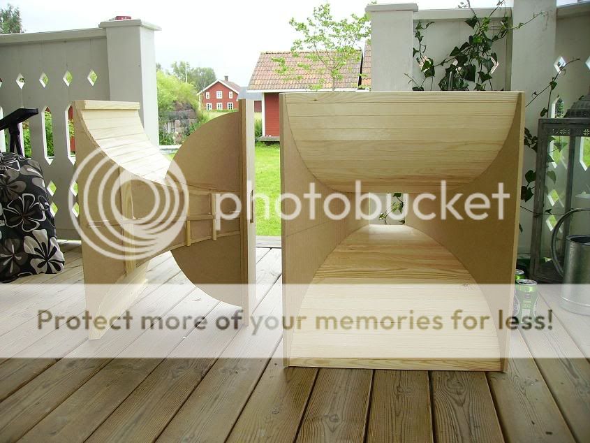
What do i choose to get it right in the text file?
Thanks
Trying to translate numbers in hornresp to an actual build.
The build im trying to achieve is something like these:
What do i choose to get it right in the text file?
An externally hosted image should be here but it was not working when we last tested it.
Thanks
Just to be sure, the attached screen capture (+ 100.0 cm) means that the Horn Mouth is 2 m from the Listener, and the Direct Radiator is 1 m from the Listener?
Hi Oliver,
Despite my best efforts, it seems that I always manage to leave things ambiguous
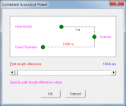
.In your screenprint, the three green dots show the positions of the two outputs relative to the listener. The red line shows the offset distance or path length difference between the two outputs. The dashed black lines show the paths from the two outputs to the listener.
The horn mouth is 1 metre from the listener and the direct radiator is 1 metre plus 100 cm, or 2 metres, from the listener.
Would either of the attached alternative representations perhaps be less confusing? (I think I prefer the second one).
Kind regards,
David
Attachments
What do i choose to get it right in the text file?
Hi sladdbarn,
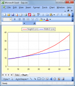
The settings shown in your screenprint should give you what you want.
The horn side panels will flare as illustrated in the attachment (the blue profile is a straight line).
Kind regards,
David
Attachments
Hi Kees,
Just to explain why I was interested in seeing a copy of the exported record file...
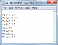
In the attached extract from the file Fr2 = 369.70 and Tal2 = 51. This means that segment 2 is 51 percent filled with absorbent material having an airflow resistivity of 369.7 mks rayls/m.
It would seem that my original "guesstimate" of 300 mks rayls/m and 50 percent was not too far off the mark.
Kind regards,
David
Would it be possible to export a copy of the Hornresp record and post the *.txt file? Thanks.
Just to explain why I was interested in seeing a copy of the exported record file...
In the attached extract from the file Fr2 = 369.70 and Tal2 = 51. This means that segment 2 is 51 percent filled with absorbent material having an airflow resistivity of 369.7 mks rayls/m.
It would seem that my original "guesstimate" of 300 mks rayls/m and 50 percent was not too far off the mark
.Kind regards,
David
Attachments
Less confusing if all the dimensions are in the same units.Hi Oliver,
Despite my best efforts, it seems that I always manage to leave things ambiguous
In your screenprint, the three green dots show the positions of the two outputs relative to the listener. The red line shows the offset distance or path length difference between the two outputs. The dashed black lines show the paths from the two outputs to the listener.
The horn mouth is 1 metre from the listener and the direct radiator is 1 metre plus 100 cm, or 2 metres, from the listener.
Would either of the attached alternative representations perhaps be less confusing? (I think I prefer the second one).
Kind regards,
David
I think for what you show that neither m, nor mm, would look good, then I have to accept cm.
cm is a unit I abhor.
Hi chaps, thanks for responding so quickly.
The problem was that double clicking didn't change anything past Fr1 Segment 0 (I could see and alter the stuffing sliders, but not for anything relevant for this design), but this seems to have sorted itself out now.
Cheers
Chris
The problem was that double clicking didn't change anything past Fr1 Segment 0 (I could see and alter the stuffing sliders, but not for anything relevant for this design), but this seems to have sorted itself out now.
Cheers
Chris
Posts #4466 and #4470
Post #4470
Hi David,
I agree, your second alternative looks like the least confusing to me. There you are showing both distances as you are using them in the simulation (?).
I think what confused me was the example in Post #4466: "...The path length difference is the distance from the port outlet to the listener minus the distance from the direct radiator diaphragm to the listener.
The difference is positive when the distance from the port outlet to the listener is greater than the distance from the direct radiator diaphragm to the listener."
I picked a +100.0 cm path length difference, and the above description seems to say to me, that the port outlet (mouth) is further away from the listener than the direct radiator diaphragm?
Regards,
Hi Oliver,
The only slight reservation I have is that the second alternative does not show the path length difference specifically. This is why I went for the original layout initially - because it definitively shows the offset between the two outputs as a solid red line.
Ah, now I see how the confusion could have arisen.
The text description I included applies specifically to the example I used, that is, to a direct radiator in a vented-box enclosure (which by definition in Hornresp has the direct radiator as output 1 and the port outlet as output 2).
"The path length difference is the distance from the port outlet (output 2) to the listener minus the distance from the direct radiator diaphragm (output 1) to the listener."
Looking again at my original schematic (Attachment 1):
Distance from the port outlet to the listener = 1 metre
Distance from the direct radiator to the listener = 20 cm + 1 metre = 1.2 metres
Path length difference = 1 metre - 1.2 metres = -20cm, which is what the slider shows.
"The difference is positive when the distance from the port outlet to the listener is greater than the distance from the direct radiator diaphragm to the listener."
By specifying a negative path length difference value in my example, in effect the reverse to the above statement applies, that is - "the difference is negative when the distance from the direct radiator diaphragm to the listener is greater than the distance from the port outlet to the listener".
Which is what my schematic shows.
In your case, you specified a back-loaded horn (which by definition in Hornresp has the horn mouth as output 1 and the direct radiator as output 2).
The applicable statement in your case becomes:
"The difference is positive when the distance from the direct radiator (ie output 2) to the listener is greater than the distance from the horn mouth (ie output 1) to the listener."
Which is what your schematic (Attachment 2) shows.
If you ignore the text description (which perhaps I should remove from the Help file to avoid any ongoing confusion, because it also just applies to a direct radiator in a vented-box enclosure) does viewing the original schematic in isolation make sense - that is, is it clear that the direct radiator is further away from the listener than is the port outlet, and that the offset difference is 20 cm?
You can probably gather by now that I would rather keep the original schematic if at all possible (for the reason given in my first paragraph) provided that it is going to be correctly interpreted by users - it's really just a matter of forgetting about any past and possibly misleading text descriptions, and simply noting the positions of the three green dots relative to each other.
I guess another option could be to revert back to the original text-based input form...
Kind regards,
David
I agree, your second alternative looks like the least confusing to me. There you are showing both distances as you are using them in the simulation.
The only slight reservation I have is that the second alternative does not show the path length difference specifically. This is why I went for the original layout initially - because it definitively shows the offset between the two outputs as a solid red line.
I think what confused me was the example in Post #4466: "...The path length difference is the distance from the port outlet to the listener minus the distance from the direct radiator diaphragm to the listener.
The difference is positive when the distance from the port outlet to the listener is greater than the distance from the direct radiator diaphragm to the listener."
I picked a +100.0 cm path length difference, and the above description seems to say to me, that the port outlet (mouth) is further away from the listener than the direct radiator diaphragm?
Ah, now I see how the confusion could have arisen
.The text description I included applies specifically to the example I used, that is, to a direct radiator in a vented-box enclosure (which by definition in Hornresp has the direct radiator as output 1 and the port outlet as output 2).
"The path length difference is the distance from the port outlet (output 2) to the listener minus the distance from the direct radiator diaphragm (output 1) to the listener."
Looking again at my original schematic (Attachment 1):
Distance from the port outlet to the listener = 1 metre
Distance from the direct radiator to the listener = 20 cm + 1 metre = 1.2 metres
Path length difference = 1 metre - 1.2 metres = -20cm, which is what the slider shows.
"The difference is positive when the distance from the port outlet to the listener is greater than the distance from the direct radiator diaphragm to the listener."
By specifying a negative path length difference value in my example, in effect the reverse to the above statement applies, that is - "the difference is negative when the distance from the direct radiator diaphragm to the listener is greater than the distance from the port outlet to the listener".
Which is what my schematic shows.
In your case, you specified a back-loaded horn (which by definition in Hornresp has the horn mouth as output 1 and the direct radiator as output 2).
The applicable statement in your case becomes:
"The difference is positive when the distance from the direct radiator (ie output 2) to the listener is greater than the distance from the horn mouth (ie output 1) to the listener."
Which is what your schematic (Attachment 2) shows.
If you ignore the text description (which perhaps I should remove from the Help file to avoid any ongoing confusion, because it also just applies to a direct radiator in a vented-box enclosure) does viewing the original schematic in isolation make sense - that is, is it clear that the direct radiator is further away from the listener than is the port outlet, and that the offset difference is 20 cm?
You can probably gather by now that I would rather keep the original schematic if at all possible (for the reason given in my first paragraph) provided that it is going to be correctly interpreted by users - it's really just a matter of forgetting about any past and possibly misleading text descriptions, and simply noting the positions of the three green dots relative to each other
.I guess another option could be to revert back to the original text-based input form...
Kind regards,
David
Attachments

Last edited:
I guess another option could be to revert back to the original text-based input form...
I should have perhaps clarified that the messages were context-sensitive in that they automatically changed depending upon the outputs involved (either direct radiator diaphragm, horn mouth or port outlet) and that they took into account which one was output 1, and which one was output 2.
Kind regards,
David
Hi David
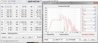
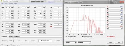
I time ago I was busy with a tapped horn and try to solve the cone correction, a lot of people dit try, and and even number of people has not exact solution with damage the woofer, this afcourse in the PA bussiness not for home.
I post some pictures where I have use the vtc and atc, I did measure the cone surface with rise, it give a lower number then with hornresp driver volume calculation sho did 2181 cc and with rise i get 1330 cc.
I have include the baffle, make atc such thet it is like the baffle thickness 1.8 cm and vtc is speaker + baffle cutout.
Now I can make the S1 and S2 smaller so that respons is good, and see that now I have included cone corrections without the possible cone damage and there is no obstruction in the horn throat.
Did I do this the right way? I did see that respons did better then without that correction.
Now I can do this also in the mouth, include there the driver magnet displacement.
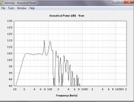
On last photo you see that it has quite a high sensitivity, 105 dB 1 watt fire from corner, a little coil do smoothe things out..
regards
kees
I time ago I was busy with a tapped horn and try to solve the cone correction, a lot of people dit try, and and even number of people has not exact solution with damage the woofer, this afcourse in the PA bussiness not for home.
I post some pictures where I have use the vtc and atc, I did measure the cone surface with rise, it give a lower number then with hornresp driver volume calculation sho did 2181 cc and with rise i get 1330 cc.
I have include the baffle, make atc such thet it is like the baffle thickness 1.8 cm and vtc is speaker + baffle cutout.
Now I can make the S1 and S2 smaller so that respons is good, and see that now I have included cone corrections without the possible cone damage and there is no obstruction in the horn throat.
Did I do this the right way? I did see that respons did better then without that correction.
Now I can do this also in the mouth, include there the driver magnet displacement.
On last photo you see that it has quite a high sensitivity, 105 dB 1 watt fire from corner, a little coil do smoothe things out..
regards
kees
Attachments
Last edited:
- Home
- Loudspeakers
- Subwoofers
- Hornresp