I hope that in evaluating the multiple speaker SPL output level you will not loose the radiator size and frequency dependent relationship of the acoustic radiation resistance.
Hi Oliver,
Please see my reply on the other thread
") .
.http://www.diyaudio.com/forums/subwoofers/170771-single-sheet-th-challenge-128.html#post2850191
Kind regards,
David
Vented Box Enclosures & Multiple Ports?
Hi David
I am re-tuning some direct radiator vented box enclosures.
I was using Hornresp and checking the results with WinISD alpha.
(WinISD makes it possible to add a filter so I can set the hipass on my DSP crossover)
When I set WinISD to use a single round port with one flanged end, the results for port length and tuning agree with the Hornresp data.
To Quote the WinISD Alpha Help file
'End correction factor is analytically or empirically determined factor, how much port extends beyond its physical ends. For free end, end correction is 0.30665 times port effective diameter. For flanged end, more analytical expression is available, 4/(3·pi) ~= 0.42441 times port effective diameter. Flanged end is calculated assuming that tube terminates to infinite baffle. Which is not exactly true, but.. Following table summarizes various port configuration types and their total end correction factors
Summary of end correction values Port configuration end correction 1 end correction 2 Total end correction
Two free ends 0.30665 0.30665 = 0.6133
One flanged and one free end 0.42441 0.30665 = 0.7311
Two flanged ends 0.42441 0.42441 = 0.8488
Physical port length is obtained by subtracting port effective diameter multiplied by suitable end correction value from port's acoustical length.'
My problem is that I want to use multiple ports. In this case I have 2 ports of 10.3cm diameter. If I use Winisd I get a different physical port length for 2 ports.
Ap is 166.65 sq cm = 1 port 14.56 cm dia = 2 ports 10.3cm dia
For a resonant frequency of 50Hz
Single port - length is quoted as 6.4cm WinISD and Hornresp
2 ports - WinISD quotes 9.55 cm
End Comensation Calc..
14.56 X 0.732 = 10.66cm
10.3 x 0.732 = 7.54cm
Difference is 3.12cm
6.4 + 3.12 = 9.52cm nearly the quoted length in WinISD.
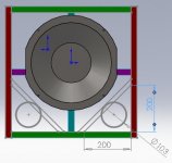
In the first instance could you confirm that my assumption that Hornresp is assuming a single round port with one flanged end (as shown in the Schematic), and as such it is using a end correction value of 0.731 x the effective port diameter?
I would like to be able to calculate the length for multiple ports.
In this case I am retuning an old speaker - and the ports are too small at Xmax levels.
To increase the size of the ports I would need to be able to calculate a effective length for 2 ports shaped like right angled triangles.
Any insights into how to calculate the port lengths would be appreciated.
Kind Regards
Martin (Xoc1)
Hi David
I am re-tuning some direct radiator vented box enclosures.
I was using Hornresp and checking the results with WinISD alpha.
(WinISD makes it possible to add a filter so I can set the hipass on my DSP crossover)
When I set WinISD to use a single round port with one flanged end, the results for port length and tuning agree with the Hornresp data.
To Quote the WinISD Alpha Help file
'End correction factor is analytically or empirically determined factor, how much port extends beyond its physical ends. For free end, end correction is 0.30665 times port effective diameter. For flanged end, more analytical expression is available, 4/(3·pi) ~= 0.42441 times port effective diameter. Flanged end is calculated assuming that tube terminates to infinite baffle. Which is not exactly true, but.. Following table summarizes various port configuration types and their total end correction factors
Summary of end correction values Port configuration end correction 1 end correction 2 Total end correction
Two free ends 0.30665 0.30665 = 0.6133
One flanged and one free end 0.42441 0.30665 = 0.7311
Two flanged ends 0.42441 0.42441 = 0.8488
Physical port length is obtained by subtracting port effective diameter multiplied by suitable end correction value from port's acoustical length.'
My problem is that I want to use multiple ports. In this case I have 2 ports of 10.3cm diameter. If I use Winisd I get a different physical port length for 2 ports.
Ap is 166.65 sq cm = 1 port 14.56 cm dia = 2 ports 10.3cm dia
For a resonant frequency of 50Hz
Single port - length is quoted as 6.4cm WinISD and Hornresp
2 ports - WinISD quotes 9.55 cm
End Comensation Calc..
14.56 X 0.732 = 10.66cm
10.3 x 0.732 = 7.54cm
Difference is 3.12cm
6.4 + 3.12 = 9.52cm nearly the quoted length in WinISD.
In the first instance could you confirm that my assumption that Hornresp is assuming a single round port with one flanged end (as shown in the Schematic), and as such it is using a end correction value of 0.731 x the effective port diameter?
I would like to be able to calculate the length for multiple ports.
In this case I am retuning an old speaker - and the ports are too small at Xmax levels.
To increase the size of the ports I would need to be able to calculate a effective length for 2 ports shaped like right angled triangles.
Any insights into how to calculate the port lengths would be appreciated.
Kind Regards
Martin (Xoc1)
Attachments
Martin,I would like to be able to calculate the length for multiple ports.
In this case I am retuning an old speaker - and the ports are too small at Xmax levels.
To increase the size of the ports I would need to be able to calculate a effective length for 2 ports shaped like right angled triangles.
Any insights into how to calculate the port lengths would be appreciated.
Kind Regards
Martin (Xoc1)
The triangular corner ports will tune lower than round ducts of the same area and length, there are various calculators on line showing differences between “slot ports” and round ducts.
By putting an "L" on the inside end of the port, it will tune lower yet, allowing for less cabinet space being reduced by the larger port.
I have measured differences in Fb between various types of port termination, but can’t help with the math.
My approach since discovering some gross errors between predicted and actual Fb (not using Hornresp) has been to simply make the ports a bit long, check the Fb visually, then reduce port length if Fb is too low.
Art
win isd pro has this error corrected.
Could you be more specific?
Is Hornresp correct, and WinISD Alpha wrong with multiple ports!????
I see 2890-120101 but no update here.
Hi Dan,
The 2890-120101 release fixed a very subtle bug in the Loudspeaker Wizard. It had no bearing on the accuracy of the results so I didn't bother to announce the change.
I have just fixed another similar low-impact bug associated with the main input parameters screen. Product Number 2890-120126 refers.
Kind regards,
David
Hi Martin,
Hornresp assumes a single circular port tube, but not as shown in the schematic. In practice the port tube is normally positioned internally, so for the purposes of the simulation model the unflanged end is considered to be inside the enclosure and the flanged end is considered to the port opening in the enclosure baffle.
Hornresp adds a length correction of 8 / (3 x Pi) x (0.5 ^ 0.5) times the port effective radius to the unflanged end inside the enclosure. No length correction is necessary at the flanged end because unlike WinISD, the actual acoustical impedance load on the port is used in the calculations.
Sorry, but I have no suggestions as to how the end corrections for multiple triangular ports could be calculated.
Kind regards,
David
In the first instance could you confirm that my assumption that Hornresp is assuming a single round port with one flanged end (as shown in the Schematic), and as such it is using a end correction value of 0.731 x the effective port diameter?
Hornresp assumes a single circular port tube, but not as shown in the schematic. In practice the port tube is normally positioned internally, so for the purposes of the simulation model the unflanged end is considered to be inside the enclosure and the flanged end is considered to the port opening in the enclosure baffle.
Hornresp adds a length correction of 8 / (3 x Pi) x (0.5 ^ 0.5) times the port effective radius to the unflanged end inside the enclosure. No length correction is necessary at the flanged end because unlike WinISD, the actual acoustical impedance load on the port is used in the calculations.
Any insights into how to calculate the port lengths would be appreciated.
Sorry, but I have no suggestions as to how the end corrections for multiple triangular ports could be calculated.
Kind regards,
David
I had the same diskussion about port end correction with the german author of Ajhorn. After simulating dozens of designs, building them up for real nad comparing the results, we figured it was not necessary to bother
If one yould be very picky about the behaviour of ports, we would also have to look after the exakt positioning of the port (relaitve to the transducer oder other radiation sources in the same frequency domain), the distance to the end of the port inside the enclosure to the adjancing walls, if the port is close to the floor, etc...
This site hosts a little peace of software conncerning flares on ports, I never checked if the results are any good (I only use some other soft for calculating resonances), but maybe he has some insight no the topic?
Flare-it - Free Speaker Design Software
Hello all
I have a question in regards to the throat chamber, when there is more than one driver.
If I model a horn with e.g two drivers, Hornresp shows the combined area of both SD's , Vtc and Atc. But placing two drivers in the same physical space is somewhat difficult, so obviously I need two throat chambers and perhaps two rear chambers??! (think offset horn with drivers on either side)
My question: Do i simply divide the Atc by two and keep Ltc as it is (thickness of plywood). I'm inclined to say yes, comparing it to reflex ports, but things aren't always as simple as they seem
I have a question in regards to the throat chamber, when there is more than one driver.
If I model a horn with e.g two drivers, Hornresp shows the combined area of both SD's , Vtc and Atc. But placing two drivers in the same physical space is somewhat difficult, so obviously I need two throat chambers and perhaps two rear chambers??! (think offset horn with drivers on either side)
My question: Do i simply divide the Atc by two and keep Ltc as it is (thickness of plywood). I'm inclined to say yes, comparing it to reflex ports, but things aren't always as simple as they seem.
Hi Twellmann,
The important thing is to maintain the same total chamber volumes as used in your Hornresp two-driver simulation.
The two drivers in the actual built loudspeaker can share a single rear chamber of volume Vrc and depth Lrc, or each driver can have its own separate rear chamber of volume Vrc / 2 and depth Lrc.
Similarly, the two drivers can share a single throat chamber of volume Vtc and area Atc, or each driver can have its own separate throat chamber of volume Vtc / 2 and area Atc / 2. The depth Ltc does not change.
Kind regards,
David
Great, thanks
Hi David,
Thanks again, another useful feature.
How about adding an Isobaric button to the "Driver Arrangement" window? To automatically calculate the proper T/S parameters for an isobaric pair, with the choice of series or parallel drivers resulting from the "Drivers connected..." windows. This might be another really helpful feature.
Regards,
Hi David,.
Help analyze. The Sim's look at what's wrong or not.
Thank you.
......................................................................
ID=28.80
Ang=2.0 x Pi
Eg=2.83
Rg=0.00
Fta=12.40
S1=470.00
S2=800.00
Con=59.10
F12=0.00
S2=800.00
S3=1974.00
Con=66.00
F23=0.00
S3=1974.00
S4=3705.00
Con=71.80
F34=0.00
S4=3705.00
S5=6564.00
Con=51.70
F45=0.00
Sd=1225.00
Bl=27.95
Cms=7.94E-05
Rms=8.76
Mmd=156.26
Le=1.79
Re=5.40
Nd=1
Vrc=91.00
Lrc=16.00
Ap1=0.00
Lpt=0.00
Vtc=4500.00
Atc=1250.00
Pmax=1200
Xmax=5.0
Comment=c18-650el
How about adding an Isobaric button to the "Driver Arrangement" window?
Hi Oliver,
To fully integrate a rigorous isobaric model into Hornresp would require a massive amount of work. Given that the configuration is rather specialised and of somewhat limited application, I can't see myself undertaking such an ambitious project
.It is already possible however, to generate a reasonably accurate prediction in Hornresp using a simplified isobaric model which ignores the air volume between driver diaphragms.
PROCESS:
To model an isobaric driver array in Hornresp, specify the electrical series / parallel connection using the Driver Arrangement tool, and set Sd equal to the driver diaphragm piston area of a single driver divided by the number of drivers in the array.
For example, if the diaphragm piston area of each driver in an isobaric pair is 500 sq cm then set the value of Sd in Hornresp to 250 sq cm. The Driver Arrangement tool will automatically double this back to 500 sq cm when 2S or 2P is selected.
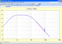
The attached chart shows the power response from one side of an isobaric driver pair connected in parallel and mounted in an infinite baffle. The red trace shows the Hornresp prediction using the simplified model and the blue trace shows the AkAbak result for the complete model - taking into account the effect of the air chamber between the two diaphragms.
The AkAbak response is marginally lower than the Hornresp response at higher frequencies due to the additional moving mass of the air volume between the drivers. The spike in the AkAbak response at 8600 hertz is due to a half-wavelength resonance in the air cavity.
For the purposes of the simulation the air volume between the drivers is assumed to be 1 litre, with the diaphragms being separated by an average distance of 2 centimetres.
Mass of 1 litre of air = 1.205 grams
Chamber half-wavelength resonance = 1 / 2 x 34400 / 2 = 8600 hertz
Kind regards,
David
Attachments
- Home
- Loudspeakers
- Subwoofers
- Hornresp