All the areas and the lengths are correct, but is there some problems in the shape?
Hi kahvis,
The Hornresp-predicted results for your proposed design should be okay. The two 90 degree bends are unlikely to significantly affect the 30-120 Hz response.
Kind regards,
David
So what effects generally would this configuration have.
Hi brsanko,
Your guess is as good as mine...
") .
.My "gut feeling" is that the overall combined response performance should not be unduly compromised, but I am not really sure.
Perhaps someone has built such a system, and can comment more authoritatively.
Kind regards,
David
Okay I know this is a tall order but would it be possible to integrate a simple crossover effect into the response graph? Like just click an option that says lowpass, high pass or band pass, and either enter a frequency or use a slider and then maybe a choice between 1st 2nd and 3rd order? Just a thought, I'm doing it in my head fairly easily but it would make it easier to see how say a tapped horn and a rear loaded horn would blend together. I know I"ve made suggestions before and you explained why it wasn't with in the scope of the program and then implemented it six month later anyway so I'll be keeping my fingers crossed. Thanks David you rock!
Last edited:
Would it be possible to integrate a simple crossover effect into the response graph?
Hi brsanko,
Sorry, it's not going to happen
.Kind regards,
David
Thanks for the reply.
I have another question about tapped horn. How this kind of tapped horn can be simulated? What about middle fold area/driver's sd ration?
I have another question about tapped horn. How this kind of tapped horn can be simulated? What about middle fold area/driver's sd ration?
An externally hosted image should be here but it was not working when we last tested it.
Hi kahvis,
Specify two drivers using the Driver Arrangement tool.
Consider total areas (ie. add the two separate mouth areas together for the purposes of the simulation).
The Sd / S2 compression ratio figure given by Hornresp automatically takes multiple drivers into account.
Kind regards,
David
How this kind of tapped horn can be simulated?
Specify two drivers using the Driver Arrangement tool.
Consider total areas (ie. add the two separate mouth areas together for the purposes of the simulation).
What about middle fold area/driver's sd ration?
The Sd / S2 compression ratio figure given by Hornresp automatically takes multiple drivers into account.
Kind regards,
David
Last edited:
Hi kahvis,
Specify two drivers using the Driver Arrangement tool.
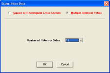
Horn segment's areas in the hornresp is all the same, like picture?
An externally hosted image should be here but it was not working when we last tested it.
Is the simulation result same for these two tapped horns? Only difference in cabinet size and pressure in s2?
Segment areas are same for whole way.
Is the simulation result same for these two tapped horns?
Hi kahvis,
The results will not be the same because of the difference in areas / volumes.
Kind regards,
David
Just what I wished for.
Hi reemoo,
Some wishes do come true then, it would seem
.Kind regards,
David
Hornresp Update
Hi Everyone,
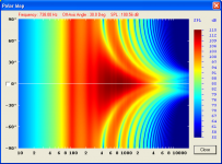
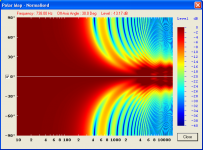
A check box has now been added to the Hornresp polar map to enable results to be shown normalised to the on-axis response, if required.
My thanks to John Sheerin for raising the issue.
Kind regards,
David
Hi Everyone,
A check box has now been added to the Hornresp polar map to enable results to be shown normalised to the on-axis response, if required.
My thanks to John Sheerin for raising the issue.
Kind regards,
David
Attachments
Hello David,
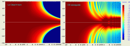
The on-axis normalization button is a great tool!
Here attached a comparison between a Le Cleac'h horn and an OS waveguide of the same dimension.
Doesn't need any coment...
Best regards from Paris, France
Jean-Michel Le Cléac'h
The on-axis normalization button is a great tool!
Here attached a comparison between a Le Cleac'h horn and an OS waveguide of the same dimension.
Doesn't need any coment...
Best regards from Paris, France
Jean-Michel Le Cléac'h
Hi Everyone,
A check box has now been added to the Hornresp polar map to enable results to be shown normalised to the on-axis response, if required.
My thanks to John Sheerin for raising the issue.
Kind regards,
David
Attachments
That's a bit misleading - you're comparing an OS horn with no round over at the mouth to your flair which does have a round over. Of course the polar map will be smoother for the LC flair in this case, but if you actually build an OS flair with a sharp corner at the mouth you are missing the point. What is obvious is that the OS even without a proper mouth termination has pretty much constant directivity within its usable bandwith while the LC flair has continuously increasing directivity.
Hello John,
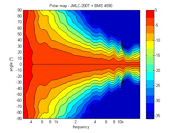
I agree that's a little bit misleading so the comparison between Hornresp results and real mesurements should be more interesting:
Real measurements for a Le Cléac'h horn:
http://www.horns.pl/images/horns/jmlc200t.jpg
polar: http://www.diyaudio.com/forums/atta...376-waveguides-horns-jmlc-200t_dir_matlab.png
real measurement for an OS waveguide having the recommanded round over at the mouth
http://www.diysoundgroup.com/images/large/OSWG_12.jpg
polar: http://www.diysoundgroup.com/images/large/OSWG_Sono.jpg
No comment again...
Best regards from Paris, France
That's a bit misleading - you're comparing an OS horn with no round over at the mouth to your flair which does have a round over. Of course the polar map will be smoother for the LC flair in this case, but if you actually build an OS flair with a sharp corner at the mouth you are missing the point. What is obvious is that the OS even without a proper mouth termination has pretty much constant directivity within its usable bandwith while the LC flair has continuously increasing directivity.
Last edited:
But couldn´t you make the "checked pattern(?)" in the printouts with thicker lines?
Hi Lars,
Just to clarify - by "checked pattern(?)" do you mean the chart gridlines?
Kind regards,
David
- Home
- Loudspeakers
- Subwoofers
- Hornresp