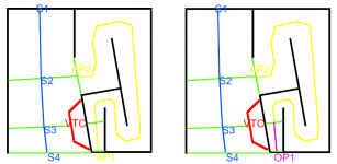
Is OP1 venting externally?
No, it's just the start of the Th (LF) path before the driver. Green lines are all the various CSA points used in the model
Last edited:
Well, your OP1 pic is basically what I was requesting from David. He stated there is too much coding to move the driver entry point.
The only difference is that this is now within the UI / UX constraints so is purely a math issue. I don't think that the community is in any rush for something like this and I wouldn't expect a change like this to be implemented overnight. But I can see the value in it and I'd be happy if it went somewhere on the backlog as an idea to explore in the future when bug fixes (if they ever) calm down.
Last edited:
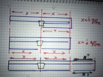
Left is where we are at the moment, right is where an offset port would get us
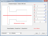
Unless I am missing something, I can't see how either configuration is possible in Hornresp. The driver, throat chamber, port 1 and port 2 are axisymmetric, as shown in the attachment. As previously advised, offsetting of the ports would require just too much work to implement.
Attachments
Unless I am missing something, I can't see how either configuration is possible in Hornresp. The driver, throat chamber, port 1 and port 2 are axisymmetric, as shown in the attachment. As previously advised, offsetting of the ports would require just too much work to implement.
Actually the basic implementation would probably look like this where Op and Con are derived from Lp1 and Lp2:
An externally hosted image should be here but it was not working when we last tested it.
It would essentially reuse the math that already in place to calculate the S1-S2-S3 horn profile values. In my suggestion the S2 equivalent could be inferred from the S1 equivalent (Ap1/Op) and S3 equivalent (Ap2). These could then be used to calculate the values for a Ap1-Driver-Ap2 horn profile. For the throat ported model the math used to generate the profile from the rear vented TH configuration could be reused (which must already allows for an interaction with Vtc/Atc) and for the rear vented model the math used to generate the profile from the throat ported TH configuration could be reused.
I had a look back though the last months worth of chat and BP1Fanatic's suggested implementation using a new Loudspeaker configuration for dual path THs (DPTH), whereby the values for Vtc are also dropped is equally valid (although removes the ability to model throat chamber effects).
In that model:
- Vtc would be the Op (S1 equivalent)
- Atc would become the area or the offset port (Aop?)
- Ap1 would be the driver location in the path (S2 equivalent)
- Lp/Lpt would be be either Con/Exp/Par (same as Lp2)
- Ap2 would be the same (S3 equivalent).
- Lp2 would be the same
I realise that this is a lot of work but either approach could be broken down and implemented slowly incrementally. For example the the addition of the Ap2 -Con/Exp/Par option in the rear vented TH model has obvious value on its own, as does the ability to switch Lp/Lpt to Con/Exp/Par in both the throat ported and vented models. Once these were in place it would be far easier to start thinking about a new Loudspeaker configuration where the driver is offset in two paths with the driver entry into the second path being located at either Ap1 (as in BP1Fanatic's example) or inferred from Ap1/Lp1-Ap2-Lp2 (as in my example).
As Paul (Booger weldz) so eloquently put it; Akabak is not the answer for most people. You've developed something here thats amazing and used by thousands of people across the world, ranging from amateur DIY enthusiasts and industry. This tool has literally lead to the evolution of new types of speaker and I'm sure it will continue to do so in the future. We are a very patient bunch and are willing to wait as long as is needed for features like these because they have the potential to solve some of the compounding issues affecting modern speaker designs in a simple, easy to use, accessible UI.
Last edited:
BP1Fanatic and thomgiles,
I am still struggling to understand exactly what it is that you are asking for. There are six tapped horn parameters available for possible re-purposing:
P1. Vrc / Ap2
P2. Lrc / Con / Cyl / Exp / Par
P3. Ap / Ap1
P4. Lpt / Lp
P5. Vtc
P6. Atc
Would it be possible to show in diagrammatic form (either schematic, or system model, or both) the configuration or configurations you are seeking, using P1 to P6 designations rather than Vrc, Lrc, etc, and for each configuration, indicating which of the P parameter values used are volumes, which are cross-sectional areas, which are lengths, which lengths are fixed cylindrical, and which lengths are flared?
Last edited:
Im wondering if there is a way to explain the desired result thats more easy to convey instead? Its far too hard to read eachothers minds in this and to try and describe a specific want and uts actual attribute without being too focused and leaving out many peoples broad ideas on a similar type of ‘pipe’. Heres one try, bare with me")
A well known pipe with a driver at its closed end or the driver at about .35 down from it makes a very nice bandwidth and with barely a hiccup in phase that can be created in OD (or TH with 0.01cm at the last segment). Perfect if the right csa is used for 3 segments of equal length nearly show this exactly.
In fact a thermoacoustic engine uses this exact location with some differential pressure created by a hot/cold split on some steel wool in a test tube in that exact location from the closed end(affective middle of its pressure phase in lengths to the closed end, then bounced out and past the driver again just in ‘time’ to create an oscillation... over and over.
Before you put other output at the end of that pipe(0.1cm path in OD or 0.01cm at the TH last segmebt) you pretty much mimic this as a qw speaker enclosure and the null forms after the 3x Fb legth, instead its at 5 or another odd harmonc interval .424 or so..
If in TH mode that can be built upon and in the same interval beyond that it will keep stretching out but still in incremebts of phase in 90/180/-90/360, etc..... inside of 720 degrees at near perfect lengths using a csa to keep the driver happy(TS parameters) 240cm (+80 cm) or 160 or 240.... repeatedly in anyway that is either a bounce or a straight length between such pressure(AC voltage) pumps from a closed end or its equivalent in a bounce off it(to and return from).
That has been used to create another popular and successful
Pair of designs known as paraflex and thus the idea is suggesting an offset driver(not closed end pipe entry as seen in the paraflex in the long(240cm pipe)
Can be used. The driver entry to the second pipe has been 80 cm away from its clised end or 0cm from it essentially and details of the driver centerline and throat chamber centerline, or rear vented chamber etc, are fudged or ignored slightly or made to work in the wooden enclosure and testing has proven that predictions of or exact results are becoming excitingly permanent known attributes of trusted and familiar shared ideas all over the entire planet.
It is HUGE! And spreads and continues to. The extension out L45 can be seperated even further this way and depending on the driver location in those intervals of (harmonics, pressure nulls) that can continue with the TH sim in so many many ways, many of which Brian Steeles notebooks now cover, but many yet to be known or widely used yet because they just were discovered last month, yesterday or just a few moments ago when i put the final 240cm on 4 segments of it that are currently a bit too big to build, but the location is being cleared or the pipes reduced with the 80/160/240cm windows it allows.
Thatskewed with a flair rate or a segmented csa increase starts to chase FLH in its performa ce at a much smaller size. This is the direct result of HORN RESPONCE and is as much yours(or even more) as anyones to be proud of! Because of this, were all in it together now. There is NO akabak, and never will be at this point in the worldwide use of your legacy. i dont know if yiu can tally the amount of downloads or increase in users but its got to be exploding because your name and the software is now regarded as the reference point to which all diy persons comminicate if successful.
Last edited:
What appears as an offset driver, is actually the distance between pipe exits, and/or the closed ends and/ or consecutive after or before pieces of the unique situation in pressure / Velocity for pipes, but also can be teased in a less than ‘perfect’ version with ‘flare’ taper, segmebts of csa change, all within these mysterious windiws of length (or close enough to persistently be observed in many many ways beyond, within or after ‘Z’ landmarks? Its truely astonishing and the ways to exploit it are even more exciting.(ill spare you the long illustrated ‘booger weldz’ version
Attachments

BP1Fanatic and thomgiles,
I am still struggling to understand exactly what it is that you are asking for. There are six tapped horn parameters available for possible re-purposing:
P1. Vrc / Ap2
P2. Lrc / Con / Cyl / Exp / Par
P3. Ap / Ap1
P4. Lpt / Lp
P5. Vtc
P6. Atc
Would it be possible to show in diagrammatic form (either schematic, or system model, or both) the configuration or configurations you are seeking, using P1 to P6 designations rather than Vrc, Lrc, etc, and for each configuration, indicating which of the P parameter values used are volumes, which are cross-sectional areas, which are lengths, which lengths are fixed cylindrical, and which lengths are flared?
Hi David:
I’m going to work with an ideal implementation (that gives the most sections to the second horn) although BP1Fanatic’s suggestion is slightly easier to understand conceptually as it doesn’t require anything to be inferred.
FYI: This would be the same for both rear vented and throat ported modes (this differentiation would not need to exist) as no chambers are defined.
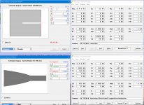
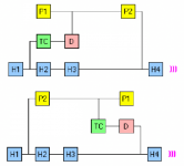
If you look in the table in the diagram below you can see how P1-6 would be used to generate equivalent values of S1,S3,S4,L1-2,L1-3 and L3-4.
You will notice that there is no S2 equivalent, this would instead be calculated based on the relationship between the CSA of the first port section (Ap1/P5), the CSA of the second port section (Ap2/P3), the expansion type (Con-Cyl-Exp-Par) and the length of the offset (Lo / P6). This model would assume that expansion profile between Ap1 and Ap2 (L1-3) would be consistent and thus the CSA at the driver entry point into the second horn (S2 equivalent) could simply be inferred.
At this point you now have equivalent values of S1,S2,S3,S4,L1-2,L2-3 and L3-4 These could then be used to generate a second horn profile using the existing math that intersects the primary horn at S1 and S4/S5.
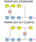
Below is an example of how this works with a simple paraflex (Cly expansion between Ap2 (P3) and Ap3 (P1), a table of the equivalent P1-6 values and description, an example of the two paraflex system models (although I believe that these essentially work out the same mathematically) using Ap1-3 as P1-3, an example of a hornsresp input window and an example of a TH Loudspeaker wizard showing the schematic 1 diagram.
An externally hosted image should be here but it was not working when we last tested it.
Last edited:
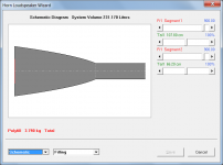
I feel like we've been here before, so please forgive me if this is the case...I am looking to explore.... sealed vs low tuned (below 20hz?) full stuffed cabinets....
So here I have matching FR figures but the vented (back loaded horn)version has been muted in output..... how do I make sense of this, I know that in real life the matching damping scenarios would definitely not mute the vented version....
Attachments
I just realised in my example P4 could also simply be L23 like in the main horn profile (rather than L13). The S2 equivalent at the driver entry point into the horn could still be inferred from the length values of P4 / P6, the CSA of P3 (Ap2) / P5 (Ap1) and the expansion profile selected in P4 (exp, con, par etc).
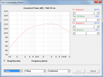
In the MLTL with Offset Port module, can you change the path length?
Yes, it should be possible to adjust the path length. Could you please post a copy of the record that does not show the path slider, so that I can investigate further. Thanks.
how do I make sense of this
As previously advised, the absorbent filling material model breaks down at very high values of Fr1. Reduce the values from 53000 mks rayls/m to something more realistic.
Attachments
I’m going to work with an ideal implementation
Thanks for the detailed response - it will take me a while to digest everything...
it will take me a while to digest everything...
thomgiles, it seems to me that you have now suggested at least six different topologies. Each configuration would require its own completely separate simulation model (all being considerably more complicated than the existing tapped horn one). This is before even beginning to address the complications that would arise in the user interface (for example, not being able to accurately represent any of the given configurations in the standard axisymmetric schematic diagram).
I fear that what you are seeking is a "step too far" for Hornresp - unfortunately I have to draw the line somewhere when it comes to these more esoteric designs. Before writing things off completely however, is there perhaps one of the six topologies that I could focus on? The first challenge would be to successfully analyse the equivalent circuit. I had a quick look at one of the configurations and identified 16 simultaneous equations that would require solving. The most I have worked with in the past is 14, in the three-way multiple entry horn loudspeaker model, and that took me two months to find a solution. The best that you could hope for is inclusion of just one of the models (your pick), but that would only be possible if I could first successfully analyse the equivalent circuit and solve the necessary equations.
Attachments
AWESOME work thomgiles!
I think BP1 fanatic, Brian Steele and Mathew Morgan J would all agree that the suggested paraflex standard model would give the most value to the community. Ignore the models with a throat chamber as they add an unneeded layer complexity (I was only using these as an illustration of how the TH system model could be extended to allow for the modeling of paraflex builds).
As I said previously, there is no rush for something like this and I'm sure that given time you could find a more elegant way of implementing an offset second horn (using P1-6) than described it in my post above. But I also think that its obvious from the last few months chat on here that conceptually this is the next logical evolution required to enable to community to push the limits of DIY speaker design.
I think it's important to note that this system model would open up the possibility for so much more than accurate paraflex simulation. By varying the CSAs, path lengths and expansion profiles of both a primary and secondary horn, this implementation would enable hornresp to simulate a whole host of new and exotic speaker topologies.
Some of the best critical thinkers in the DIY community (looking at you boogie welder) are not traditional mathematicians or programmers and thus find Akabak really clunky and unintuitive. The way that you have enabled these individuals (as well as the multitude of other, less experienced users) with the tools to continue driving speaker design forward is an amazing gift. And I would like to thank you from the bottom of my heart for even considering exploring this as an idea.
Yes, please
Affirmative,
I totally agree with what Mr Thomgiles has said here about adding this driver-offset capability in the High-Tuned resonator section of the standard method for modeling Paraflex cabinets ..... This feature (if implemented) will be tremendously useful to our development community and anyone else who is trying to model such things......
David, regardless of this feature proposal (whether it happens or not) we are as of many years now more than forever grateful for everything that you have done, to such an extent that words cannot possibly do justice when trying to convey our level of appreciation for You
- Home
- Loudspeakers
- Subwoofers
- Hornresp