To much silence.
A bug fix is most appreciated.
Thanks Mark
") .
.Hunting down even the most tiny bugs
And thank you Sabbelbacke, for your ongoing support also, in continuing to provide the download website for Hornresp!
And thank you Sabbelbacke, for your ongoing support also, in continuing to provide the download website for Hornresp!
I have never added a thank you for your services Sabbelbacke. What would we be doing without an internet host?
There are alternatives but not as easy to use.
Thanks for your time and continued support on this most interesting and useful software.
Hi all,
I’d like to clarify something about modelling multiple drivers in Hornresp.
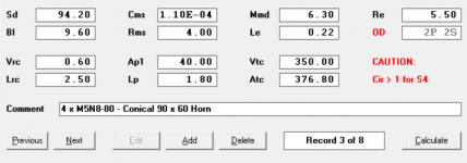
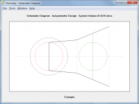
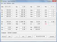
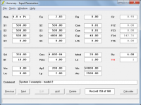
In the attached screenshot, all the entered chamber parameters result in optimal modelled performance (e.g. frequency response, phase response, driver displacement, etc.) for the project I’m working on, which is a midrange multiple entry horn.
What I’m not sure about, however, is whether the chamber parameters are correct for each of the 4 drivers, or whether they are correct for a hypothetical driver with 4 times the Sd of a single driver.
In other words, when building the design, do I want to build (for example) a rear chamber of 0.6 litres for each driver, or a rear chamber of 0.15 litres for each driver? Should (for example) the average throat chamber area be 376.8cm2 or 94.2cm2 per driver? I presume the latter is correct in both cases, but I’m not sure.
And ofc I have the same question in respect of all the chamber parameters, i.e. Vrc, Lrc, Ap1, Lp, Vtc, Atc.
Many thanks for your help
Cheers
Andreas
I’d like to clarify something about modelling multiple drivers in Hornresp.
In the attached screenshot, all the entered chamber parameters result in optimal modelled performance (e.g. frequency response, phase response, driver displacement, etc.) for the project I’m working on, which is a midrange multiple entry horn.
What I’m not sure about, however, is whether the chamber parameters are correct for each of the 4 drivers, or whether they are correct for a hypothetical driver with 4 times the Sd of a single driver.
In other words, when building the design, do I want to build (for example) a rear chamber of 0.6 litres for each driver, or a rear chamber of 0.15 litres for each driver? Should (for example) the average throat chamber area be 376.8cm2 or 94.2cm2 per driver? I presume the latter is correct in both cases, but I’m not sure.
And ofc I have the same question in respect of all the chamber parameters, i.e. Vrc, Lrc, Ap1, Lp, Vtc, Atc.
Many thanks for your help
Cheers
Andreas
Attachments
Last edited:
Hi all,
I’d like to clarify something about modelling multiple drivers in Hornresp.
In the attached screenshot, all the entered chamber parameters result in optimal modelled performance (e.g. frequency response, phase response, driver displacement, etc.) for the project I’m working on, which is a midrange multiple entry horn.
What I’m not sure about, however, is whether the chamber parameters are correct for each of the 4 drivers, or whether they are correct for a hypothetical driver with 4 times the Sd of a single driver.
In other words, when building the design, do I want to build (for example) a rear chamber of 0.6 litres for each driver, or a rear chamber of 0.15 litres for each driver? Should (for example) the average throat chamber area be 376.8cm2 or 94.2cm2 per driver? I presume the latter is correct in both cases, but I’m not sure.
And ofc I have the same question in respect of all the chamber parameters, i.e. Vrc, Lrc, Ap1, Lp, Vtc, Atc.
Many thanks for your help
Cheers
Andreas
Sorry, I should have said multiple driver horn - not multiple entry horn (the horn uses four identical drivers which enter at the same axial point along the horn, although ofc at different points around this axis; think of something like just the midrange section on a synergy horn).
EDIT: could I also take this moment to thank David for his incredible piece of software
Hi Andreas,
The answer is in the Hornresp Help file.
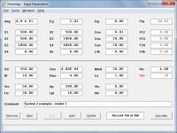
"Multiple drivers share the horn system, throat chamber and rear chamber as defined by the input parameter values and as shown in the schematic diagram."
The built rear chamber volume should be 0.15 litres for each driver.
The built average throat chamber area should be 94.2 cm2 for each driver (* Note that the throat chamber length remains constant at 0.93 cm).
Nothing changes, the principle remains the same. Hornresp chamber volumes and areas (Vrc, Ap1, Vtc, Atc) are total system values, shared across the multiple drivers. Hornresp chamber lengths (Lrc and Lp) remain constant, not affected by the number of drivers *.
Built values:
Vrc(B) = 0.60 / 4 = 0.15 litres
Lrc(B) = 2.50 cm *
Ap1(B) = 40.00 / 4 = 10.00 cm2
Lp(B) = 1.80 cm *
Vtc(B) = 350.00 / 4 = 87.50 cm3
Atc(B) = 376.80 / 4 = 94.20 cm2
Ltc = 350.00 / 376.80 = 0.93 cm
Ltc(B) = 87.50 / 94.20 = 0.93 cm (no change) *
To summarise - when building the system simply divide the Hornresp chamber volumes and areas by the number of drivers and leave the lengths unchanged.
Kind regards,
David
What I’m not sure about, however, is whether the chamber parameters are correct for each of the 4 drivers, or whether they are correct for a hypothetical driver with 4 times the Sd of a single driver.
The answer is in the Hornresp Help file
."Multiple drivers share the horn system, throat chamber and rear chamber as defined by the input parameter values and as shown in the schematic diagram."
In other words, when building the design, do I want to build (for example) a rear chamber of 0.6 litres for each driver, or a rear chamber of 0.15 litres for each driver?
The built rear chamber volume should be 0.15 litres for each driver.
Should (for example) the average throat chamber area be 376.8cm2 or 94.2cm2 per driver?
The built average throat chamber area should be 94.2 cm2 for each driver (* Note that the throat chamber length remains constant at 0.93 cm).
And ofc I have the same question in respect of all the chamber parameters, i.e. Vrc, Lrc, Ap1, Lp, Vtc, Atc.
Nothing changes, the principle remains the same. Hornresp chamber volumes and areas (Vrc, Ap1, Vtc, Atc) are total system values, shared across the multiple drivers. Hornresp chamber lengths (Lrc and Lp) remain constant, not affected by the number of drivers *.
Built values:
Vrc(B) = 0.60 / 4 = 0.15 litres
Lrc(B) = 2.50 cm *
Ap1(B) = 40.00 / 4 = 10.00 cm2
Lp(B) = 1.80 cm *
Vtc(B) = 350.00 / 4 = 87.50 cm3
Atc(B) = 376.80 / 4 = 94.20 cm2
Ltc = 350.00 / 376.80 = 0.93 cm
Ltc(B) = 87.50 / 94.20 = 0.93 cm (no change) *
To summarise - when building the system simply divide the Hornresp chamber volumes and areas by the number of drivers and leave the lengths unchanged.
Kind regards,
David
Attachments
Last edited:
Resistive vent ala Dynaco
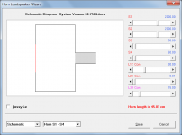
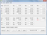
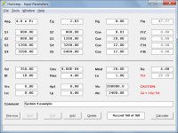
Have tried searching through this thread and have not found what I need. Question is whether one can simulate a resistive vent (classic aperiodic) enclosure like the old Dynaco speakers which were essentially a sealed enclosure with a controlled leak by means of a stuffed (i.e. resistive) vent using hornresp.
Have tried searching through this thread and have not found what I need. Question is whether one can simulate a resistive vent (classic aperiodic) enclosure like the old Dynaco speakers which were essentially a sealed enclosure with a controlled leak by means of a stuffed (i.e. resistive) vent using hornresp.
Question is whether one can simulate a resistive vent (classic aperiodic) enclosure like the old Dynaco speakers which were essentially a sealed enclosure with a controlled leak by means of a stuffed (i.e. resistive) vent using hornresp.
Hi mashaffer,
Simulate as shown in the attachment, using the Loudspeaker Wizard tool to add absorbent filling material to the port tube (vent) as required.
Kind regards,
David
Attachments
Hi mashaffer,
Simulate as shown in the attachment, using the Loudspeaker Wizard tool to add absorbent filling material to the port tube (vent) as required.
Kind regards,
David
Thx!
Thank you. It´s the least I can do, wish I could do moreI have never added a thank you for your services Sabbelbacke. What would we be doing without an internet host?
Chamber>Throat Adaptor
Hello David, how are you? I hope so.
First of all, I want to say First of all, that it is a great pleasure to have met you here, always clarifying as many doubts as possible about this incredible soft.
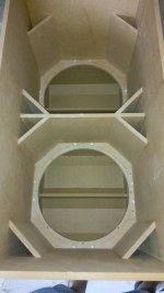
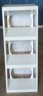
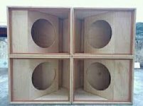
I always come across with some doubt and today was about this third option of rear camera. I would like to know if it is suitable for these enclosures I attached. If not, let me know how to do it, if possible. Thanks!
Hi Kees,
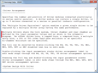
The Tools > Chamber Type menu command can have up to three menu sub-commands, depending upon the system configuration:
Rear Lined - Input parameters are Fr and Tal
Rear Vented - Input parameters are Ap and Lpt
Throat Adaptor - Input parameters are Ap1 and Lpt
(The Throat Adaptor menu sub-command becomes Throat Ported for offset driver and tapped horn systems)
To illustrate the differences between the three options:
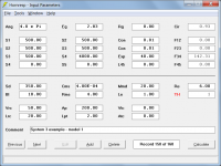
Step 1 - Make a copy of default record number 1 and change the value of Fr from 40000 to 40. Attachment 1 shows the schematic diagram. The rear chamber is sealed and lined. The acoustical lining has an airflow resistivity of Fr and a thickness of Tal.
Step 2 - Double-click on the Fr or Tal label to change to Ap and Lpt. Alternatively, select menu command Tools > Chamber Type > Rear Vented. Attachment 2 shows the new schematic diagram. The rear chamber is now unlined but vented. The port tube vent has a cross-sectional area of Ap and an axial length of Lpt.
Step 3 - Double-click on the Ap or Lpt label to change to Ap1 and Lpt. Alternatively, select menu command Tools > Chamber Type > Throat Adaptor. Attachment 3 shows the new schematic diagram. The rear chamber is now sealed and unlined but a conical throat adaptor has been inserted between the throat chamber and horn segment 1. The throat adaptor has an inlet cross-sectional area of Ap1 and an axial length of Lpt.
For offset driver and tapped horns, the throat adaptor becomes a port between the throat chamber and the entry point into the horn.
The three options will affect the system performance in different ways.
Kind regards,
David
Hello David, how are you? I hope so.
First of all, I want to say First of all, that it is a great pleasure to have met you here, always clarifying as many doubts as possible about this incredible soft.
I always come across with some doubt and today was about this third option of rear camera. I would like to know if it is suitable for these enclosures I attached. If not, let me know how to do it, if possible. Thanks!
Attachments
Hello David, how are you? I hope so.
First of all, I want to say First of all, that it is a great pleasure to have met you here, always clarifying as many doubts as possible about this incredible soft.
I always come across with some doubt and today was about this third option of rear camera. I would like to know if it is suitable for these enclosures I attached. If not, let me know how to do it, if possible. Thanks!
Hi M1 Audio,
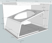
The systems shown in your Attachments 1 and 4 could perhaps be modelled as tapped horns with large throat chambers (see my attachment below).
The systems shown in your Attachments 2 and 3 would probably need to be modelled using AkAbak.
Kind regards,
David
Attachments
Hello David, how are you? I hope so.
First of all, I want to say First of all, that it is a great pleasure to have met you here, always clarifying as many doubts as possible about this incredible soft.
I always come across with some doubt and today was about this third option of rear camera. I would like to know if it is suitable for these enclosures I attached. If not, let me know how to do it, if possible. Thanks!
Hi M1 Audio,
After having another look at the loudspeaker systems shown in your Post #7936, if I am interpreting the designs correctly, it appears that it may be possible to simulate all four in Hornresp as different variants of tapped horns.
SYSTEM 1 - Simulate as shown in Attachment 1.
(Values for Ap1 and Lp can also be specified, if so desired).
SYSTEM 2 - Simulate as shown in Attachment 2 or in Attachment 3.
If simulated as shown in Attachment 3 (Model 2 considers half the total system and one driver) use the Multiple Speakers tool to specify the complete system as 2 speakers in parallel.
SYSTEM 3 - Simulate one of the 3 horn cabinets as shown in Attachment 4 or in Attachment 5.
Use the Multiple Speakers tool to specify the 3 cabinets making up the complete system.
SYSTEM 4 - Simulate as shown in Attachment 6 or in Attachment 1.
If simulated as shown in Attachment 1 use the Multiple Speakers tool to specify the complete system as 2 speakers in series together with 2 speakers in parallel.
Kind regards,
David
Attachments
Thank you. It´s the least I can do, wish I could do more
I'll help you with that
I got some sweet "ideas".
- Home
- Loudspeakers
- Subwoofers
- Hornresp